Week - 4
Automatic washing machine
Objective
Implement control logic of a “washing machine” using State flow as per given sequence:
- If the power supply is available, the system gets activated
- If the Water supply is not available, stop the process & indicate through LED
- Soaking time should be 200s followed by Washing time of 100s.
- Then rinsing happens for next 20s & dryer runs for 50s
After all the processes have completed turn on the finished LED
Model
Components
Charts
Terminators
Lamps
Rocker switch
Chart
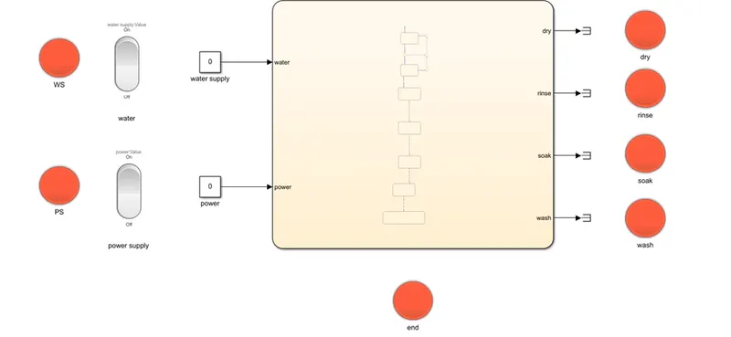
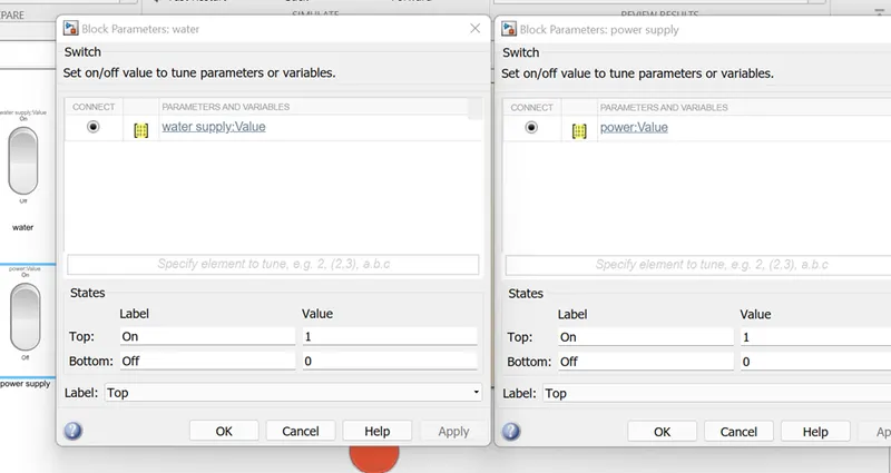
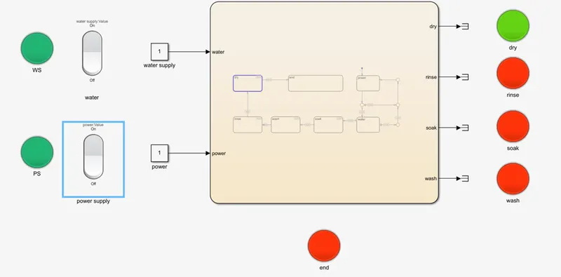
- The constant block is used to give input to input ports power and water supply
- These ports are connected to rocker switches and lamps as follows
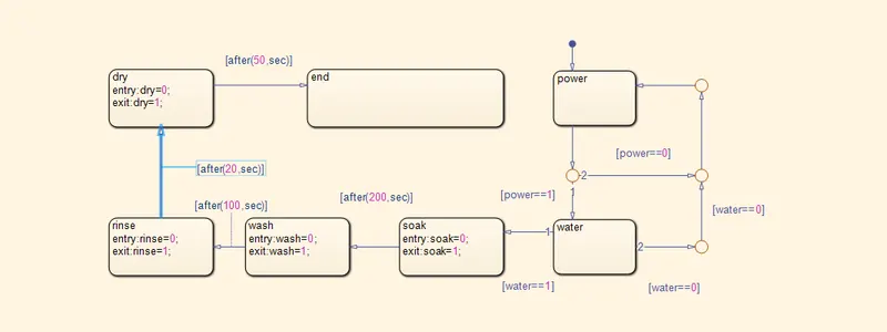
- The state flow logic is written such that if and only if
-
Water && power ==1
then the following processes start.
- The processes go from soaking, washing, rinsing, drying for 200,100,20,50 seconds respectively.
- These four states are connected to output ports as follows
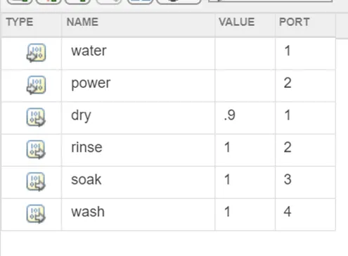
- The working of these ports is indicated by lamps
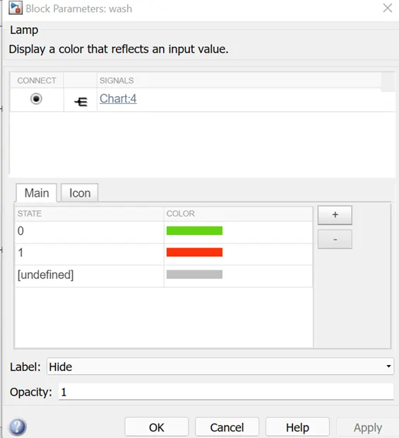
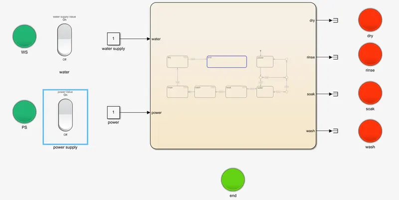
- The completion of the washing process is indicated by the end lamp which is connected to dry terminal and has following parameters

-
Results
Both switches off
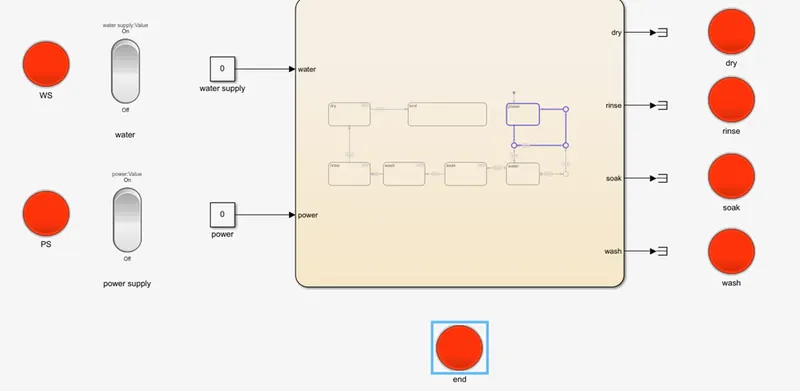
-
One switch on and the other is off
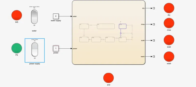
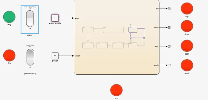
-
Both switches on
Case 1 – soaking
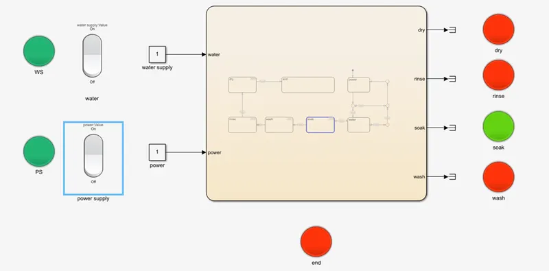
-
Case 2 – washing
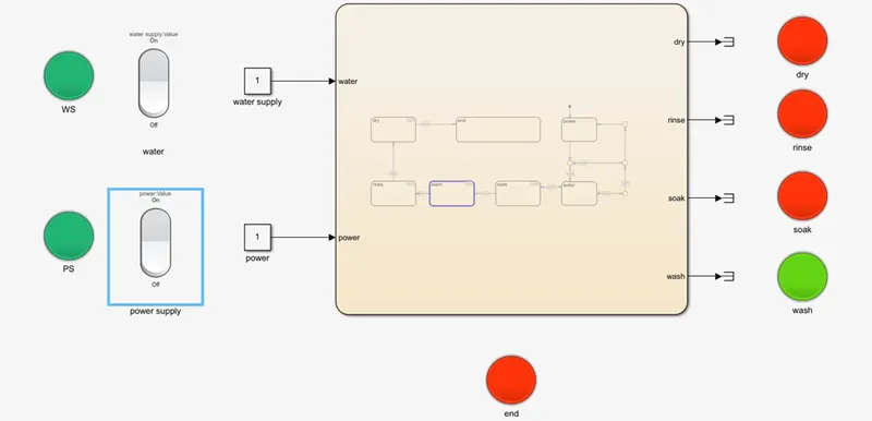
Case 3 – rinsing
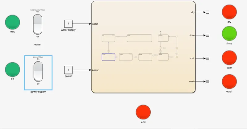
Case 4 – drying
Process end
The full working is provided in video format as well
Gear shift logic
Objective
Make a Simulink chart for the “Gear shift” logic as per below conditions:
Speed Range(kmph) Gear
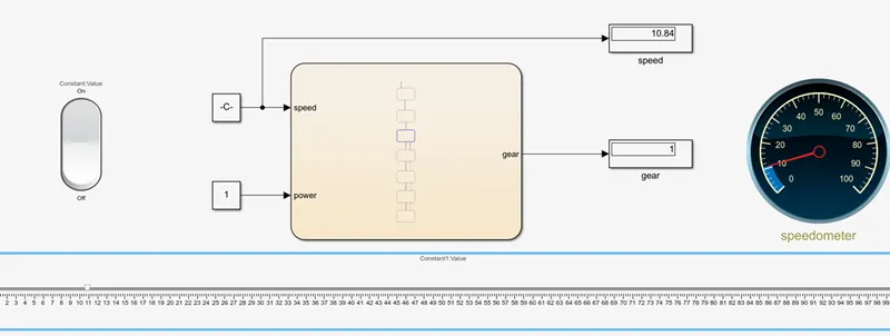
0 to 15 1
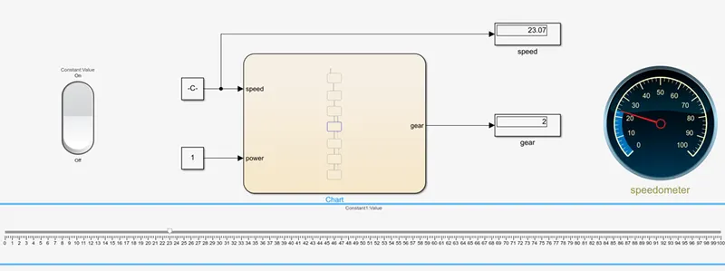
16 to 25 2
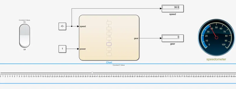
26 to 40 3
41 to 60 4
Above 61 5
Give speed input while the simulation is running & display the gear number.
Model
Components
Rocker switch
Slider
Chart
Display
Circular gauge
Chart
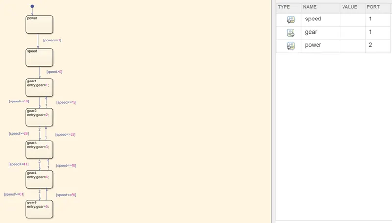
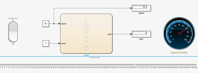
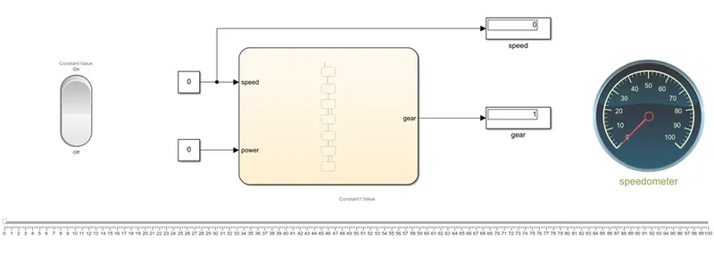
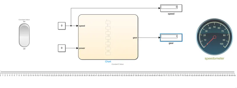
- Input is given by connecting a rocker switch to the power port to indicate that the car is on.
- Gears are initiated by if else conditions with respect to the speed parameter.
- The speed is given by using a slider and connecting it to the input port
- This helps us in changing the speed in real time just like in actual automobile and checking which gear is used in which speed range
- The gear value is displayed using display port
- The speed values are displays using a display port and a circular gauge.
Results
Power off
Power on
Case 1 – 0<speed<15
Case 2 – 16<speed<25
Case 3 – 26<speed<40
Case 4 – 40<speed<60
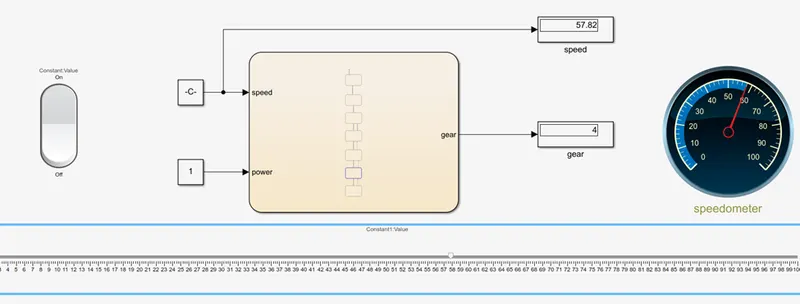
Case 5 – speed>61