Week - 4
Aim: To create simulation charts of the control logic of ‘washing machine’ and ‘ gear shaft’ as per the condition given.
Objective:
- Implement control logic of a “washing machine” using Stateflow as per given sequence:
- If the power supply is available, the system gets activated
- If the Water supply is not available, stop the process & indicate through LED
- Soaking time should be 200s followed by Washing time of 100s.
- Then rinsing happens for the next 20s & dryer runs for 50s
After all the processes have been completed turn on the finished LED
- Make a Simulink chart for the “Gear shift” logic as per the below conditions:
Speed Range(kmph) Gear
0 to 15 1
16 to 25 2
26 to 40 3
41 to 60 4
Above 61 5
Give speed input while the simulation is running & display the gear number.
Solution:
- Implement control logic of a “washing machine” using Stateflow as per given sequence:
- If the power supply is available, the system gets activated
- If the Water supply is not available, stop the process & indicate through LED
- Soaking time should be 200s followed by Washing time of 100s.
- Then rinsing happens for the next 20s & dryer runs for 50s
After all the processes have been completed turn on the finished LED
A washing machine is a machine that is used to wash various types of clothes without applying any physical effort. The washing machine allows you to wash your clothes automatically without having to supervise its operation. All you have to do is just put your clothes in the washing machine and select the wash mode. The washing machine automatically takes the amount of water and the detergent required and it also set the timer for washing, rinsing, and drying as per the selected mode and the number of clothes.
Stages of washing machine:
- Prewash
- Washing
- Rinsing
- Spinning
Modeling of washing machine in Simulink:
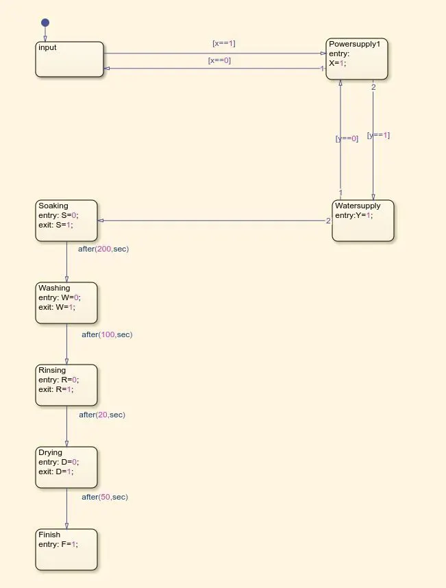
State flow chart:
Simulink model:
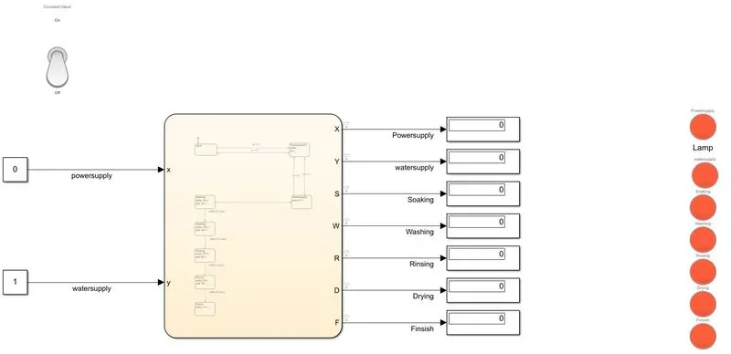
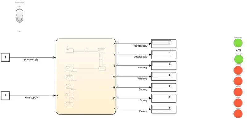
Power ON
Soaking
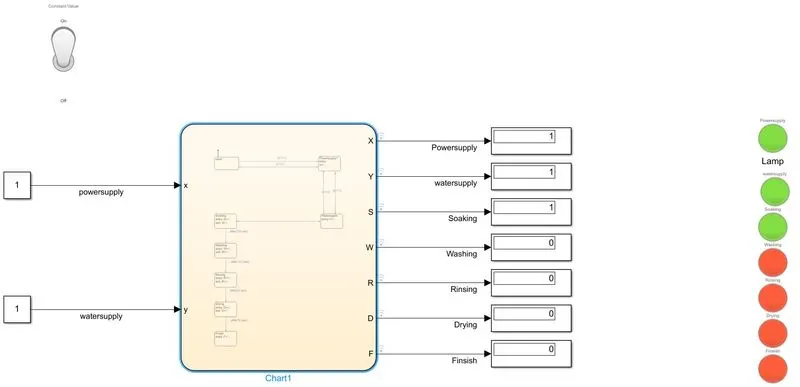
Washing ON
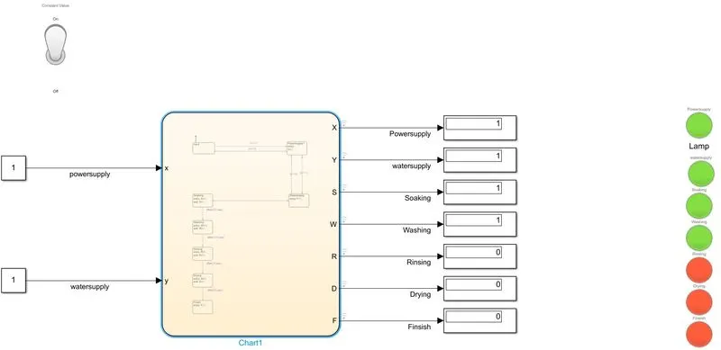
Rinsing ON
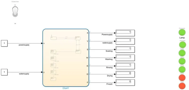
Drying and Finish
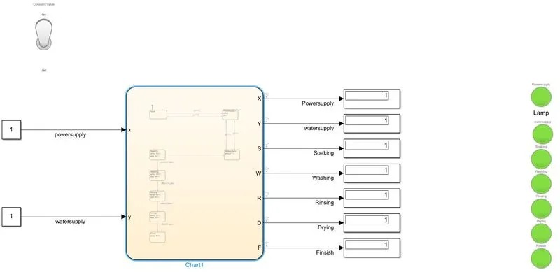
Objective:
- Make a Simulink chart for the “Gear shift” logic as per the below conditions:
Speed Range(kmph) Gear
0 to 15 1
16 to 25 2
26 to 40 3
41 to 60 4
Above 61 5
Give speed input while the simulation is running & display the gear number.
Modeling of gear shaft in Simulink:
State flow chart:

Simulink model:
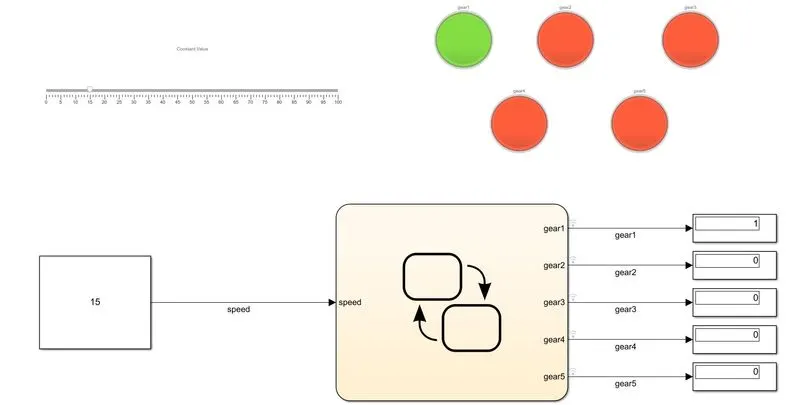
When the speed ranges between 0-15, gear1 become active:
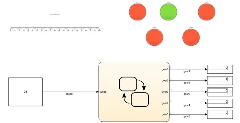
When the speed ranges between 16-25, gear2 become active:
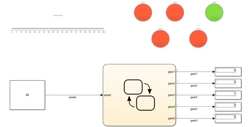
When the speed ranges between 26-40, gear3 become active:
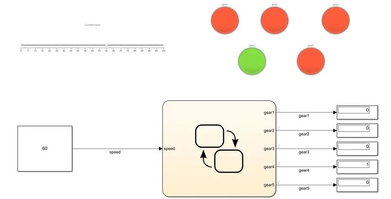
When the speed ranges between 40-60, gear4 become active:
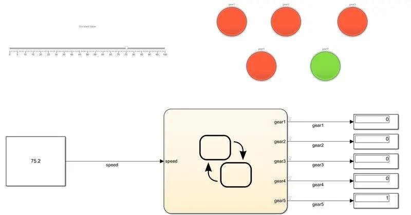
When the speed ranges above 60, gear5 become active: