Project 1
Assume the output voltage ripple is less than 1%
--> δVo/Vo=0.01 and
switching frequency fs=100kHz
1. BUCK CCM:
Vi=40V to 50V , Vo=30V, Po=500 W
D= Vo/Vi, R=V2oPo=302500=1.8ohm
--> range of D= 3040→3050=0.75→0.63040
Caclulation of circuit parameters:
Indutance:
Lmin=(1−D)∗R2∗fs
Lmin=2.25μH,3μH
In order for inductor current to be continuous for variable input voltage, we must choose an inductance value larger than the greatest value of Lmin found.
so let's take L=5μH
Capacitance:
Co≥1−D8∗f2s∗L∗δVo/Vo
Co≥62.5μF,100μF
so let's take Co=150μF
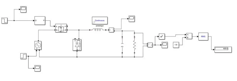
Simulation: At t= 2sec, the input voltage is changed from 40V to 50V, and the duty ratio is changed from 0.75 to 0.6 to maintain the appropriate output voltage. The simulation takes 3 seconds to complete.
Simulation results:
Output voltage:
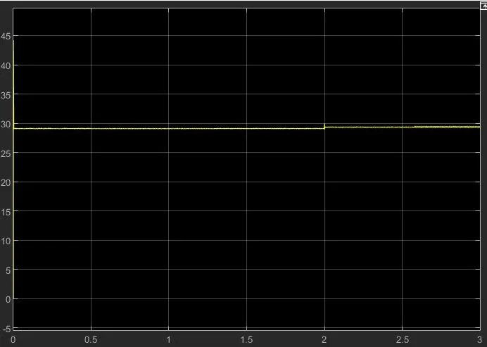
Because the ON state decreases of the diode and voltage are not taken into account, the output voltage is somewhat less than 30V.
Zoomed plot:
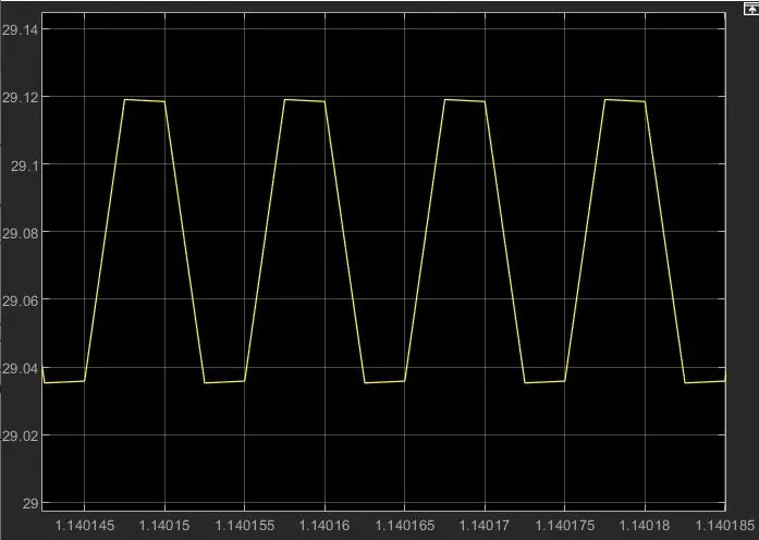
The ripple voltage is 29.04-29.12=0.08V, which is less than 1% of the output voltage
=> 0.01*30=0.3V, indicating that the designed capacitor meets the design criteria.
Inductor current:
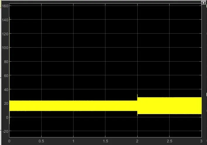
The inductor current is substantially over 0A, implying that it is constant, making this converter a Buck converter in continuous conduction mode. When the input voltage is changed from 40V to 50V, the ripple inductor current rises.
Ripple current in the inductor,
δIL=(Vi−Vo)∗DL∗fsδIL=(Vi-Vo)∗DL∗fs
so at 2sec product of (Vi-Vo)*D also increases
=> 10*0.75 to 20*0.6 =>7.5 to 12V
since deltaIL is proportional to Vi-Vo * D , ripple also increases.
Power output:
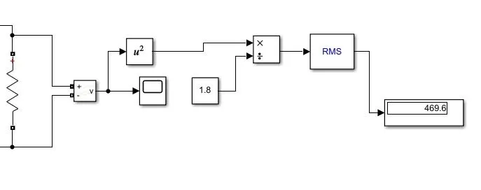
The formula V^2/R is shown in the block diagram above for calculating output power. Because the voltage is somewhat lower, the power is likewise lower than 500W. (desired).
BUCK CCM:
Vi=400V to 500V,
Vo=300V,
Po=5000W
D= Vo/Vi, R=V2oPo=30025000=18ohmR=Vo2Po=30025000=18ohm
=> range of D= 300400→300500=0.75→0.6300400→300500=0.75→0.6
Calculation of circuit parameters:
Inductance:
Lmin=(1−D)∗R2∗fs
Lmin=22.5μH,36μHLmin=22.5μH,36μH
In order for inductor current to be continuous for variable input voltage, we must choose an inductance value larger than the greatest value of Lmin found. Let's use L=47HL=47H as an example.
Capacitance:
Co≥1−D8∗f2s∗L∗δVo/Vo
Co≥26.59μF,42.5μF
so let's take Co=47μFCo=47μF
Simulation results:
At t= 2sec, the input voltage is changed from 400V to 500V, and the duty ratio is changed from 0.75 to 0.6 to maintain the appropriate output voltage. The simulation takes 3 seconds to complete.
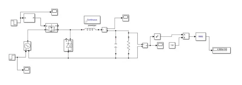
Simulation results:
Output voltage:
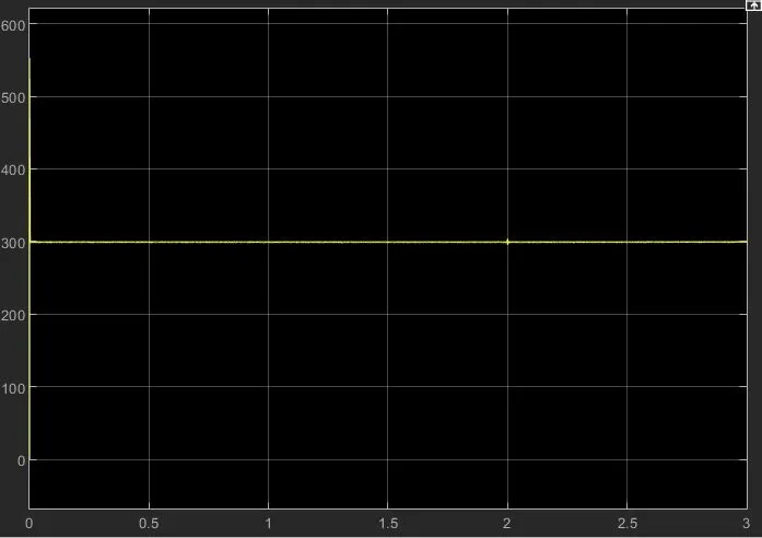
Because the ON state decreases of the diode and voltage are not taken into account, the output voltage is somewhat less than 30V.
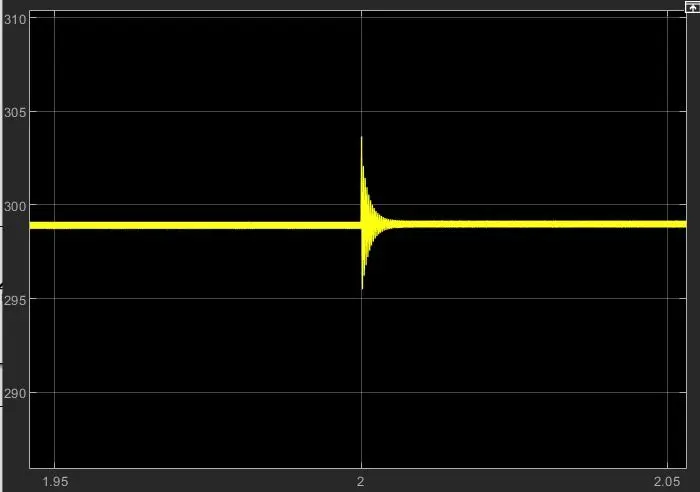
zoomed in the plot:
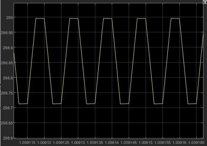
The ripple voltage is 298.7-299=1.3V, which is less than 1% of the output voltage
=> 0.01*300=3V, indicating that the designed capacitor meets the design criteria.
Inductor current:
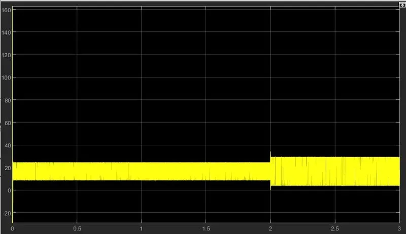
The inductor current is substantially over 0A, implying that it is constant, making this converter a Buck converter in continuous conduction mode. When the input voltage is changed from 400V to 500V, the ripple inductor current rises.
Ripple current in the inductor,
δIL=(Vi−Vo)∗DL∗fsδIL=(Vi-Vo)∗DL∗fs
so at 2sec prodcut of (Vi-Vo)*D also increases
=> 100*0.75 to 200*0.6 =>75 to 120V
since deltaIL is proportional to Vi-Vo * D , ripple also increases.
Power output:
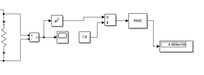
The formula V^2/R is shown in the block diagram above for calculating output power. Because the voltage is lower, the power is likewise lower than 5000W. (desired).
Boost Converter: CCM
Vi= 20V to 40V, Vo=30V, Po=600W
=> R=V2oPo=402600=83ohmVo2Po=402600=83ohm
Circuit:
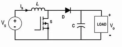
Vo=Vi1−DVo=Vi1-D, D= duty ratio
=> D=D=Vo−ViVoD=Vo-ViVo
substituting the values of Vi is the above equation, we get a range of duty ratio
⇒D=40−3040→40−2040⇒D=40-3040→40-2040
D=0.25 to 0.5
Calculation of circuit parameters:
Inductance:
Lmin=D⋅(1−D)2∗R2∗fs
⇒Lmin=1.667μH,1.875μH
In order for inductor current to be continuous for variable input voltage, we must choose an inductance value larger than the greatest value of Lmin found.
so let's take L=4.7μHL=4.7μH
Capacitance:
Co=Dfs∗R∗δVo/Vo
⇒Co=187μF,93.75μF
To keep the output ripple under control, we need to choose a Co value that is bigger than the previous values.
so let Co=220μF
Simulation:
Model:
At t= 2sec, the input voltage is changed from 20V to 30V, and the duty ratio is changed from 0.5 to 0.25 to maintain the desired output voltage. The simulation takes 3 seconds to complete.
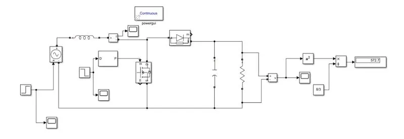
results:
Output voltage:
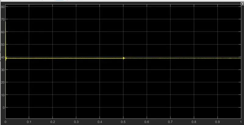
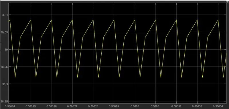
In both situations (39.1-38.8=0.3V) and (39.1-38.9=0.2V), the ripple voltage voltage is less than the expected ripple of 1 percent => 0.01*40=0.4V. As a result, the design considerations are addressed by the capacitor.
Inductor current:
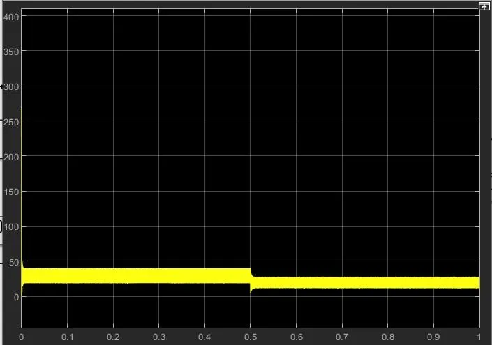
In all situations, inductor currents are much over 0A, implying that the current is constant regardless of the input voltage.
When the input voltage is changed from 20V to 30V, the ripple is inductor current and the average current drops.
Ripple current in the inductor,
δIL=(Vi)∗DL∗fsδIL=(Vi)∗DL∗fs
so at 2sec product of (Vi-Vo)*D also increases
=> 20*0.5 to 30*0.25 =>10V to 7.5V
since deltaIL is proportional to Vi* D , ripple also increases.
.
Power:
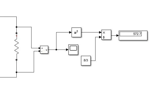
The formula V^2/R is shown in the block diagram above for calculating output power. Because the voltage is somewhat lower, the power is likewise lower than 600W. (desired).