Week -2
Aim: The is to design a Simulink model of a doorbell using a solenoid block and design another Simulink model of a thermistor to sense the temperature of a heater & turn on or turn off the fan.
Objective:
- Design a Simulink model of doorbell using a solenoid block with the following details:
In the above arrangement, when the switch is closed the electromagnets receives electrical power from battery and pulls the metal arm to hit the bell producing sound.
Create a situation where the switch is closed for 2 sec and then released. Observe the physical movement of the plunger. Assume remaining parameters.
- Use a thermistor to sense the temperature of a heater & turn on or turn off the fan as per the below conditions:
Temperature source: 20 ℃ from 0 to 10 seconds, 27 ℃ from 10 to 30 seconds, 23 ℃ from 30 to 50 seconds.
Fan conditions: ON if the temperature above 25 ℃, OFF otherwise
Solution:
Objective – 1: The doorbell principle is based on magnetic field where the armature gets attracted to the magnetic field and this magnetic field is produced by copper windings when electricity is passed through it.
Simulation model
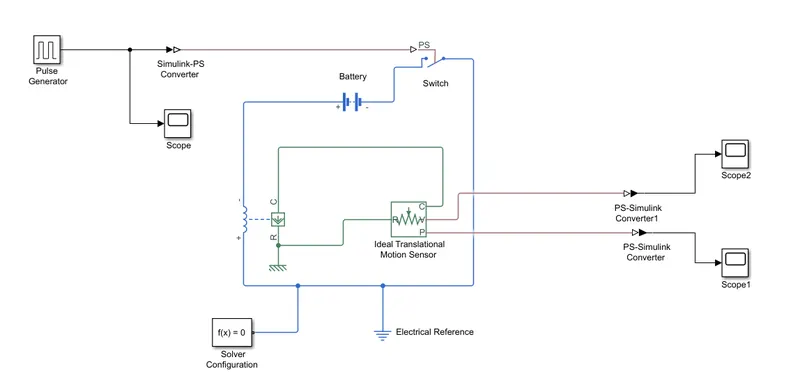
Process of flow
Pulse generator generate the pulse for every 2 sec to control the switch to ring the bell. The generated signal from pulse generator is plotted and converted into real time environment. This signal controls the current through the solenoid. When current passes through the solenoid generate the magnetic field which attract the iron armature. Ideal motion sensor is used to sense the motion and then signals are converted to Simulink phase to record the motion of the hammer.
Results:
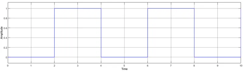
- Amplitude plot: Time pulse is generating for every 2 second to control the switch
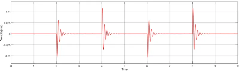
- Velocity plot:
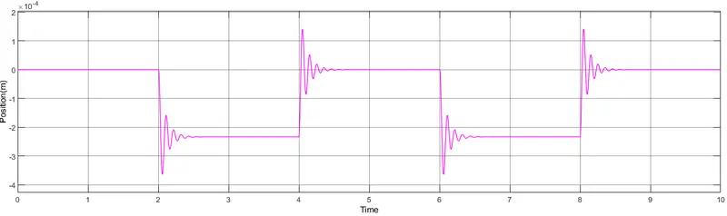
- Position plot: we can observe that switch is closed for 2 second and after that switch is open.
We can also observe that plunger strikes after every 2 seconds.
Objective-2:
The model completely depends on thermistor , it is a type of resistor whose electrical resistance varies with temperature changes. And sensed resistance is used to generate voltage respectively to control a circuit. Thermistor act as a passive component in a circuit , it is basically a two terminal solid state thermally sensitive transducer constructed using sensitive semiconductor based matel oxides with metallised or sintered connecting leads formed into a ceramic disc or bead. This allows thermistor to change its resistive value in proportion to small change in ambient tempreture.
Simulink model
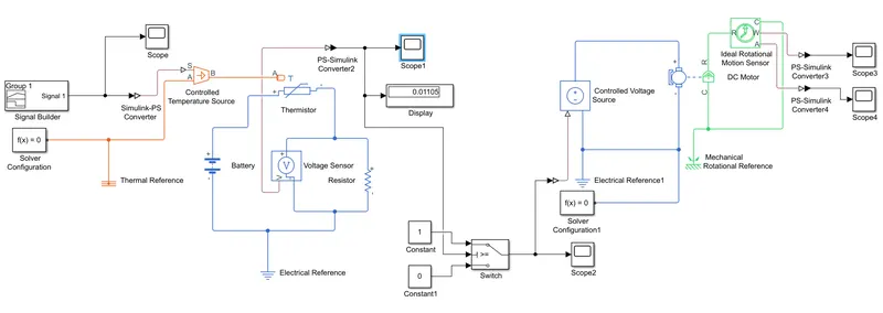
Process of flow
Signal builder is used to generate temperature signal at various time interval
Condition of heat source
T = 293.15 K for time 0 to 10 second
T = 300 K for time 10 to 30 second
T = 296.15 K for time 30 to 50 second
Condition for FAN
T = 25 degree Celsius > ON
T = 25 degree Celsius < OFF
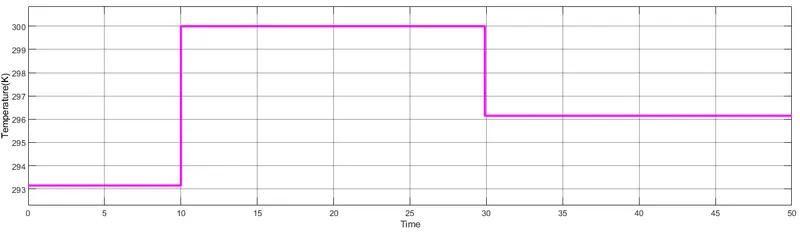
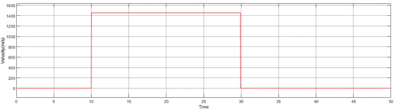
This temperature data is passed through the thermistor to sense and generate the resistance value accordingly . As the resistance is changed according to the current (i) voltage is sensed across it using voltage senser(voltmeter) . Further the voltage is inputted in to (threshold controlled ) switch for turning ON the motor. Then the particular value of voltage temperature (T = 27 degree Celsius ) turn on the motor. Using the ideal rotational motion sensor the activities of the motor is obtained and the velocity and angular displacement variation shown in figure.
Results:
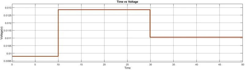
Time vs voltage
From the figure we can say voltage is generating as the temperature varies with respect to time.
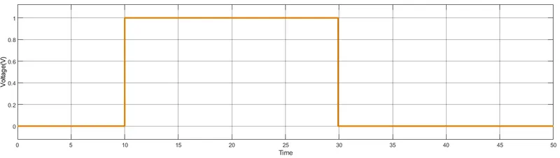
Time vs Controlled voltage
From the figure we can sat that voltage is obtained for 10 to 30 second at T = 27 degree Celsius to turn on the motor
Time vs Velocity
Time vs Angular Displacement
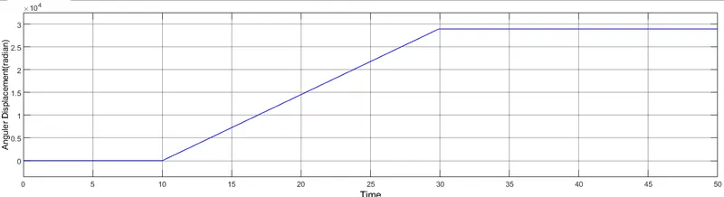
Above two figure shows that as the temperature exceeds t = 25 degree Celsius DC motor is turned ON, here t = 27 degree Celsius is grater than 25 degree Celsius hence motor gets turned ON.