Week - 4
ANSWER 1
Aim:-
To Implement control logic of a “washing machine” using Stateflow.
Conditions:-
- If the power supply is available, the system gets activated
- If the Water supply is not available, stop the process & indicate through LED
- Soaking time should be 200s followed by Washing time of 100s.
- Then rinsing happens for the next 20s & dryer runs for 50s.
- After all the processes have been completed turn on the finished LED.
Working Principle of Washing Machine:-
- The main principles behind the working of a washing machine are the centrifugal and centripetal forces, Where centrifugation helps quicken the process of sedimentation of different density particles to clean the laundry in the washing machine.
- The washing machine operates in two primary cycles. These are the wash cycle and the rinse cycle.
- The wash cycle involves the principle of centrifugal force. This force’s direction is from inside to outside, which makes sure that every part of the cloth is rinsed adequately in the soap water mixed in the machine.
- The rinse cycle involves the principle of centripetal force. This force acts from outside to inside and creates a vacuum-like space in the middle of the washing machine.
- These two cycles work one after another several times, and as a result, the entire cleaning process occurs.
Control logic of washing machine with the help of state flow:-
- Stateflow is a control logic tool used to model reactive systems via state machines and flow charts within a Simulink model.
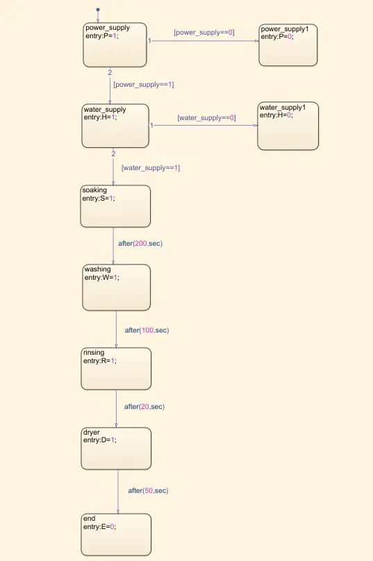
- As we can see in the above chart which is a state flow block in Simulink, which can be used to create control logic in it.
- The above chart creates a state flow that represents the logic control of the washing machine.
- In every state, the entry value is defined by which the process is on or off for on condition we use 1 constant and for off condition we use 0 constant.
- The power supply state is used as input to the Stateflow. We define power supply as a P variable, where P=1 defines as the system is in on condition. on the other side, there is another power supply state where P=0 defines as there is no power supply that's why the system is off which is connected with the help of default transition tool to give the direction of flow.
- The water supply state is connected to the power supply with the help of the default transition tool which defines the power is on [power_supply==1]. The water supply state is defined by variable H where H=1 which means the system is on. On the other hand, the water supply state is connected to another water supply state where H=0 which is the system will turn off if there is no water supply.
- The water supply state is connected to the soaking state in condition when the water supply is on (H=1) with the help of the default transition tool. Soaking is defined as variable S where S=1 which means the process is on.
- The soaking state is later connected to the washing state which is defined by the variable W in between these the value provided to the default transition tool is after(200, sec) which means the soaking time is 200 sec after the 200-sec washing process takes place in washing state the value is W=1 which means the washing process is on.
- The washing state is connected to the rinsing state which is known by the variable R, where R=1 means the rinsing process is on. As we can see the rinsing process is on after 100 sec of the washing process which means the washing process will run for 100 sec.
- The rinsing process is run for the next 20 sec, later the rinsing state is connected to the dryer state which is defined by the variable D. Where D=1 is given which means the dryer process is on. The dryer process carries out for the next 50 sec as we can see in the above diagram.
- After 50sec the process ends that's why we connected the end state to the dryer state.
- With these, we successfully create the logic control for the washing machine with the help of Stateflow.
Simulink Block Diagram:-
Simulink Block Used:-
- constant
- chart
- display
- lamp
Simulink Block Explanation:-
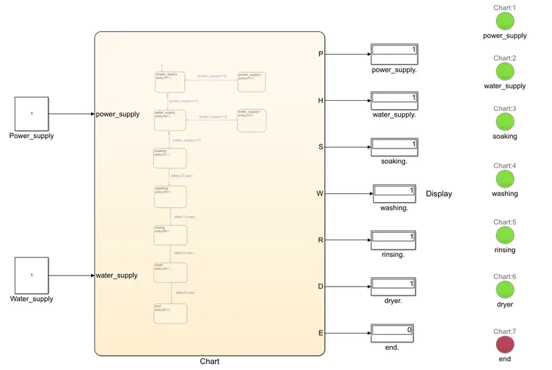
- The above Simulink block diagram represents the washing machine with a logic control chart in the flowstate.
- The constant blocks are used to provide values to the chart block in terms of power supply and water supply, the values are provided are for on condition is 1 and for the off condition is 0.
- Display block is used to get output values in terms of to check the system is on or off.
- The lamp is used to indicate that whether the system is on or off which is connected to the display blocks.
Output/Result:-
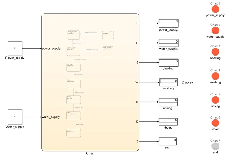
For condition: Where the power supply is off (power supply = 0) then the system will not activate.
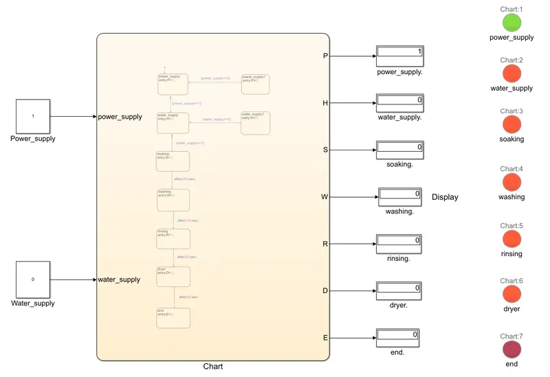
For condition: where power supply is on (power supply = 1) but the Water supply is not available (water supply=0) then
For condition: where power supply is connected (power supply = 1) and water supply is also connected (water supply = 1) then
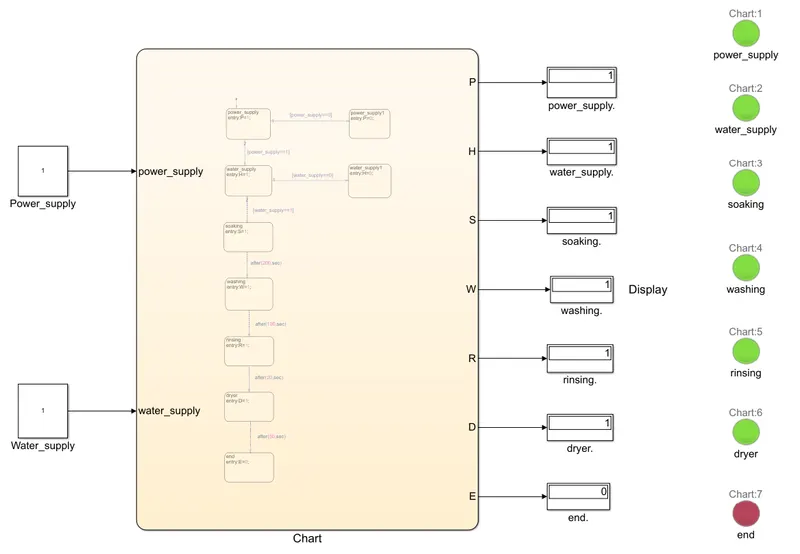
Here Green lamp defines the process is on and Red lamp defines the process is stopped or off.
Answer 2
Aim:-
To make a Simulink chart for the “Gear shift” logic as per the below conditions.
Conditions:-
Speed Range(kmph) Gear
0 to 15 1
16 to 25 2
26 to 40 3
41 to 60 4
Above 61 5
Give speed input while the simulation is running & display the gear number.
Stateflow Chart:-
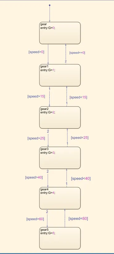
- The above Stateflow chart shows the control logic of the Gear shift mechanism where speed is input value and gear is output value.
- In the Stateflow diagram as shown above for all states, we have an entry for gear where gear is defined by variable G.
- The first state Gear indicates that there is no speed input that's why we can say the gear is in the neutral condition where we have the value of G=0.
- The first state gear0 is connected to state gear1 with the help of the default transition tool where the conditions are if speed>0 then it proceeds to gear1 and if the speed==0 then it returns to its neutral condition.
- Same for gear1 if the speed>15 then it shifts toward gear2 and if speed<15 then it comes in gear1 condition.
- If the speed>25 then it shifts toward gear3 and for condition speed<25 it's in gear2.
- For the condition speed>40 then it shifts towards the gear4 and if speed<40 it's in gear3.
- And for the condition where speed>60 it's in gear5 and if the condition speed<60 the gear4 condition occurs.
- With the help of Stateflow, we made logic control of the gear shift mechanism.
Simulink Block Diagram:-
Simulink Block Used:-
- Circular Guage
- Slider
- Chart
- constant
- Display
- lamp
Simulink Block Explanation:-
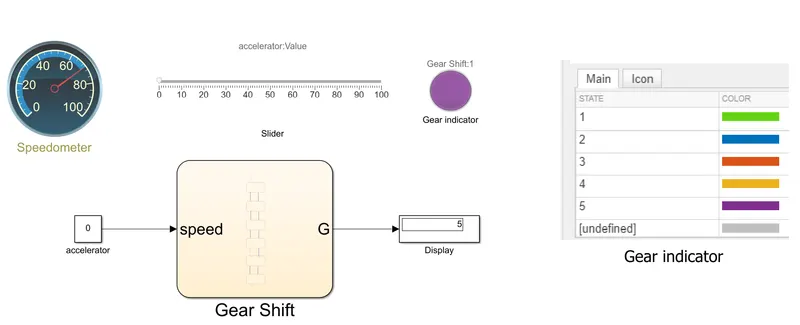
- The constant block is used which is connected to the slider block which provides the input values in the form of speed.
- The chart block is connected to a constant which gives input values and is also connected to the display block which gives output values in the form of gear.
- A circular gauge block is used which is named a speedometer is used to display the speed values which is connected to the constant block.
- lamp block is connected to display block which indicates the gear according to the given colours as we can see in the Simulink block diagram.
- With the help of the above block, we implant the Gear mechanism with the help of Stateflow and Simulink.
Result/Output:-
- when the speed is between 0-15 kmph then it's in first gear.
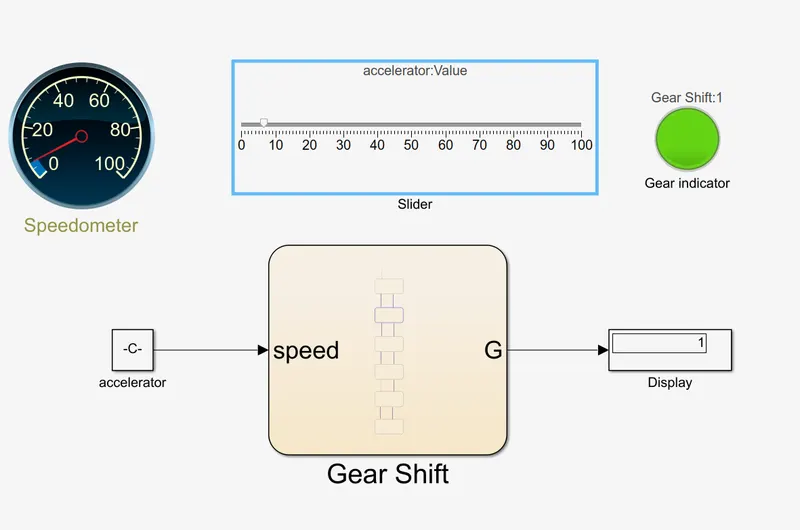
- When the speed is between 16-25 kmph then it's in second gear.
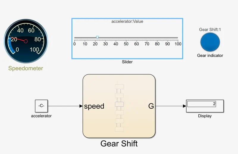
- When the speed is between 26-40kmph then it's in third gear.

- When the speed is between 40-60kmph then it's in fourth gear.
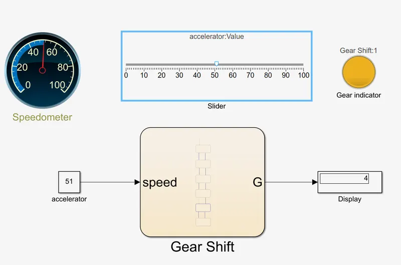
- When the speed is between 60 or above then it's in fifth gear.
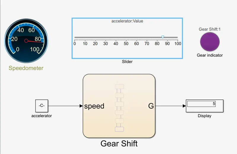
The above diagram shows that the simulation of gear shift according to the given condition of speed has been completed successfully.