Week -2
1. Doorbell
Aim:-
To create a Simulink model of doorbell using solenoid block.
Condition:-
Create a situation where the switch is closed for 2 seconds and then released. Observe the physical movement of the plunger.
Simulink Model:-
Simulink Blocks Used:-
- Pulse Generator
- Simulink-PS converter
- battery
- switch
- electrical reference
- solenoid
- Ideal translational motion sensor
- mechanical translational reference
- solver configuration
- PS-Simulink converter
- scope
Simulink Model Explanation:-
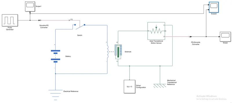
In the above model, the PULSE GENERATOR block is used to provide pulse waves at regular time intervals. The parameters of the PULSE GENERATOR block are amplitude, period, pulse width, and phase delay, with the condition mentioned above.
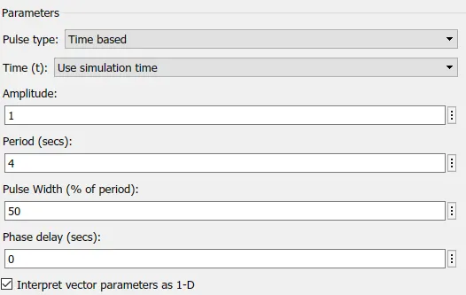
The Simulink-PS converter is connected to the SWITCH block, which provides physical values in the form of input from the pulse generator to the switch block.
The Solenoid block is connected to the positive port of a switch and the negative port is connected to the battery and Electrical reference.
Which form the complete electric circuit.
The R port of the solenoid block is connected to the R port of the Ideal translational motion sensor and the C port the of solenoid block is connected to the C port the of Ideal translational motion sensor.
The ideal translational motion sensor is used to sense the movement of the plunger which is connected to Mechanical translational Reference and solver configuration.
The p port of the Ideal translational motion sensor connects to the PS-Simulink converter which converts the physical signals to Simulink signals.
The scope is connected to an Ideal translational motion sensor and PS-Simulink converter to get output which is the movement of Plunger.
Output/Result:-
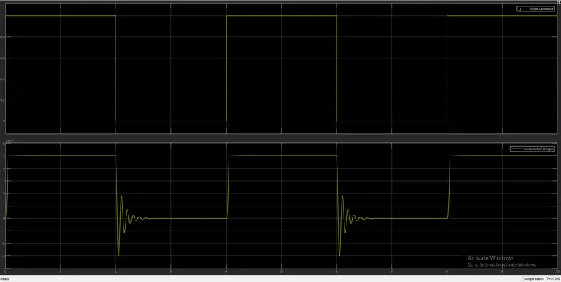
The above graph shows the Pulse generator and movement of plunger.
In the first block we observe the input where the circuit is closed for 2 sec and then its realsed.
The second blocks shows the movement of plunger when the circuit is closed for 2 sec and then its opened.
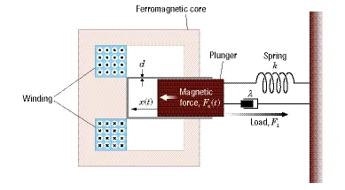
The above fig is off the solenoid when we provide the input in the form of current the plunger moves towards port C because that spring will expand and when current goes off then spring will return to its initial position. which causes a damping effect. As for this Simulink model we need to provide some metal blocks to produce the sound of the bell when the plunger hits the metal block its rings the bell.
Conclusion:-
With the help of we created the Simulink model of doorbell using solenoid block successfully.
2. Thermister
Aim:-
To use a thermistor to sense the temperature of a heater & turn on or turn off the fan.
Condition:-
Temperature source: 20 °C from 0 to 10 seconds, 27 °C from 10 to 30 seconds, 23 °C from 30 to 50 seconds
Fan conditions: ON if the temperature is above 25 °C, OFF otherwise.
Simulink Model:-
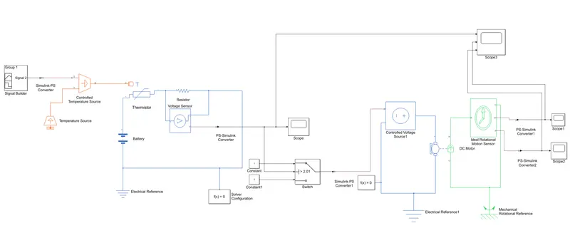
Simulink Blocks Used:-
- Signal Builder
- Simulink-PS converter
- Controlled Temperature source
- Temperature source
- Thermistor
- Resistor
- voltage sensor
- Battery
- Electrical referance
- PS-Simulink converter
- constant
- solver configuration
- switch
- scope
- Controlled voltage source
- DC motor
- Ideal rotational motion sensor
- Mechanical Rotatioanl referance
Simulink Model Explanation:-
In the Simulink model as shown above we use a Thermistor block, the thermistor is a type of resistor whose resistor is reliant on temperature, in this NTC type thermistor is used.
The thermistor is connected with the positive port of the battery which provides the required voltage and the negative port is connected to the voltage sensor which is used to measure voltage and resistor block along with the electrical referance block. Which form the complete electric circuit.
Signal builder block is used to give input signals connected to the Simulink-ps converter to the S port of the controlled temperature source, which provides values based on a given condition. A port of Controlled temperature source is connected to the Temperature source block.
Thermisters A port is connected to B port of controlled temperature source to receive input values.
The voltage output port is connected to Ps-Simulink converter which converts physical signals to respective Simulink signals, PS-Simulink converter is connected to Scope which gives the output.
PS-Simulink converter is also connected to Switch block. Switch block getting voltage signals is also connected to two Constant blocks which provide constant values which are 1 and 0. This Switch block has three ports, port 2 is the input source the switch has a 2.01 threshold value.
This switch is connected to a Controlled voltage source that controls the input of voltage. This controlled voltage sensor is connected to a DC motor, Positive and negative ports of the Controlled voltage source are connected to the positive and negative ports of the DC motor.
DC motor block is a reference block for a fan cause there is no such block in Simulink for the fan. The C and R ports of the DC motor are connected to the Ideal Rotational motion sensor. An ideal rotational motion sensor is used to sens the motion of a DC motor.
The W and A ports of the Ideal rotational motion sensor are connected to the PS-Simulink converter, this PS-Simulink conveters converts physical values to Simulink values, which are connected to the scope which gives output values from the Ideal rotational motion sensor.
The input data provided to the Signal builder block is given below are time values at [0 10 10 30 30 50] and temperature values are [293 293 300 300 296 296].
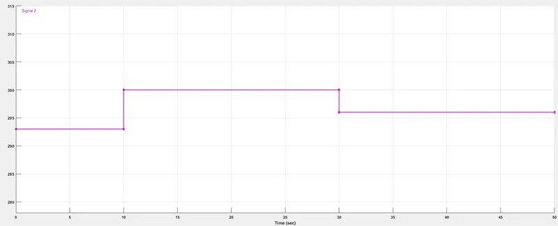
From the above graph, the input data for signal Builder Block is Time in sec are from 0 to 50, and Y-axis which is the temperature difference.
For 0-10sec temperature is at 293k,
For 10-30sec temperature is at 300k,
For 30-50sec temperature is at 296k.
Result:-
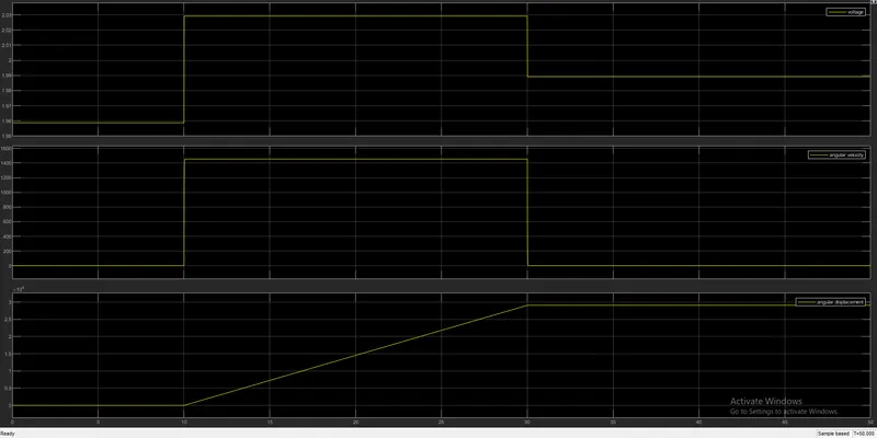
The above graph shows the Output of the Simulink block we created.
The first block shows the voltage difference changes with respect to time, the second graph shows the angular velocity with respect to time and the third block shows the angular displacement with respect to time. The time axis is of 50 sec.
For the time period of 0-10 sec, the temperature is at 20 °C hence voltage, angular velocity, and angular displacement is at 0. for the time period of 10-30 sec the temperature is at 27 °C which satisfy our condition hence we can see in the graph the voltage is at 2.03 and angular velocity is at 1300rpm and angular displacement is increasing to 2.08. And for the time period of 30-50 sec where the temperature is at 23 °C the voltage and angular velocity graph started to decrease but angular displacement remain constant.
The above graph shows how the fan is off for 0-10sec then it is on for 10-30sec and again off for the next 30-50sec which satisfies our condition.