Week - 4
AIM:
- To implement control logic of a “washing machine” using Stateflow as per given sequence:
- If the power supply is available, the system gets activated
- If the Water supply is not available, stop the process & indicate through LED
- Soaking time should be 200s followed by Washing time of 100s.
- Then rinsing happens for next 20s & dryer runs for 50s
After all the processes have completed turn on the finished LED
2. To Make a Simulink chart for the “Gear shift” logic as per below conditions:
Speed Range(kmph) Gear
0 to 15 1
16 to 25 2
26 to 40 3
41 to 60 4
Above 61 5
Give speed input while the simulation is running & display the gear number.
DESCRIPTION:
STATE FLOW:
1. WASHING MACHINE
The state flow of washing machine has 7 stages in general
i, Cloth filling cycle
ii, water loading cycle
iii, agitating cycle
iv, rinse cycle
v, spin cycle
vi, drain cycle
vii, drying cycle
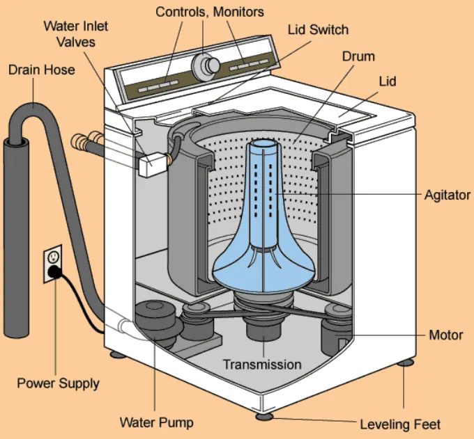
the working of the washing machine is explained in detail in the below link
but in this assignment only few states are discussed :
PROCEDURE:
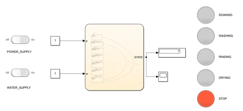
1. The CHART block is created for creating the state control logic of a washing machine.
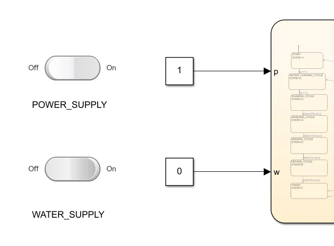
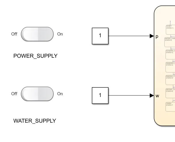
2. The 2 main input parameters are assumed as power supply (p) and water supply (w).
3. LAMP blocks are created to indicate the working state of the washing machine using state variables linked to chart
4. A ROCKER SWITCH block is created to indicate the condition of POWER SUPPLY and WATER SUPPLY.
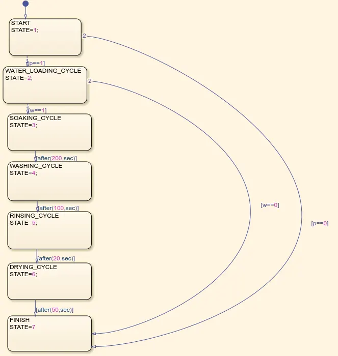
5. 7 state boxes are created as shown below to define the states of the washing machine.
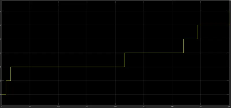
6. The machine was run for 400 seconds and the resuts are taken from the scope block.
7. When there is power supply and no water supply, the state returns to the finish state.
8. Only when there is power supply and water supply, the machine runs its 7 states as displayed
9. The inputs are p and w and the output is STATE and is defined in the symbols pane
STATE FLOW CHART OF A WASHING MACHINE
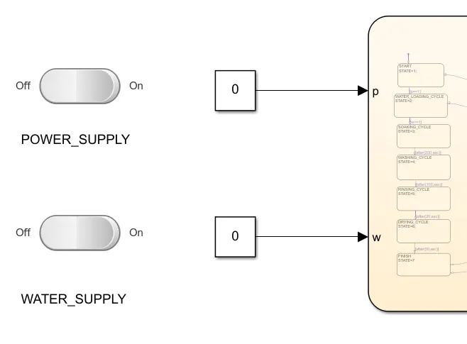
CONDITION 1: NO POWER SUPPLY, NO WATER SUPPLY.
CONDITION 2: POWER SUPPLY with NO WATER SUPPLY.
CONDITION 2: POWER SUPPLY with WATER SUPPLY.
2. GEAR POSITION INDICATOR:
The gear position of the vehicle has to be changed in manual transmission whenever the vehicle reaches a threshold rpm. The gear position indicator displays the GEAR POSITION whenever the vehicle reaches the particular speed. This will be very much helpful for the beginners to shift the gear at the right time and also to avoid revving more which will reduce the fuel efficiency. A simulink model is created to display the gear position indicator whenever the vehicle reaches certain speed.
PROCEDURE:
1. The CHART block is created for creating the state control logic of a GEAR POSITION INDICATOR.
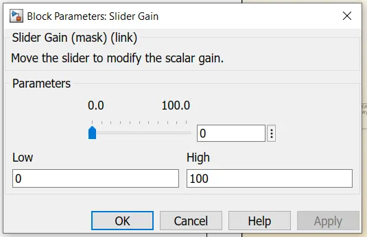
2. A GAUGE Block is created to display the speed at which the vehicle is moving and is connected to the slider gain where the speed input is given.
3. According to the given conditions of speed and gear shift, the values are entered in the chart and using symbol pane, speed is given as input and GEAR is given as output.
4. Using SCOPE block and DISPLAY block, the gear position indicator can be read.
GEAR POSITION INDICATOR:
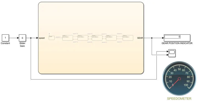
STATE FLOW CHART OF THE GEAR INDICATOR:

RESULTS:
1. WASHING MACHINE:
CONCLUSION:
The results shows that the soaking was done for 200s and washing for 100s, rinsing for 20s and drying for 50s.
2. GEAR POSITION INDICATOR:

CONCLUSION:
The results shows the gear positon changes when the slider gain reaches the particular speed range.