Week -2
AIM:
1. Create a Bell arrangement and close the switch for 2 seconds and observe the plunger movement
1. Use a thermistor to sense the temperature of a heater and turn on or off the fan based on the given conditions.
REPORT:
BELL ASSIGNMENT
PROCEDURE:
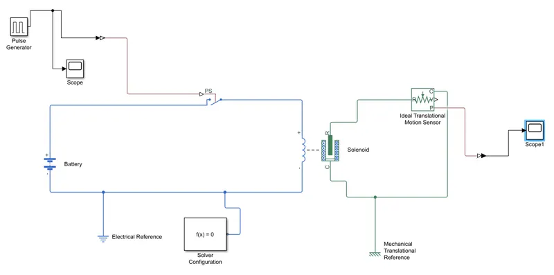
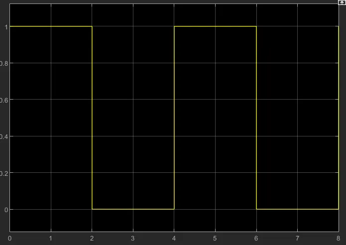
1. The input signal is given in the PULSE GENERATOR BLOCK form for 4 seconds and 50 percent pulse width.
2. The input signal can be visualized in the SCOPE BLOCK which is connected to the PULSE GENERATOR BLOCK.
3. A BATTERY BLOCK is created and is connected to the SOLENOID BLOCK. A solenoid is a copper winded coil which is capable of producing magnetic field around it when current is passed through it.
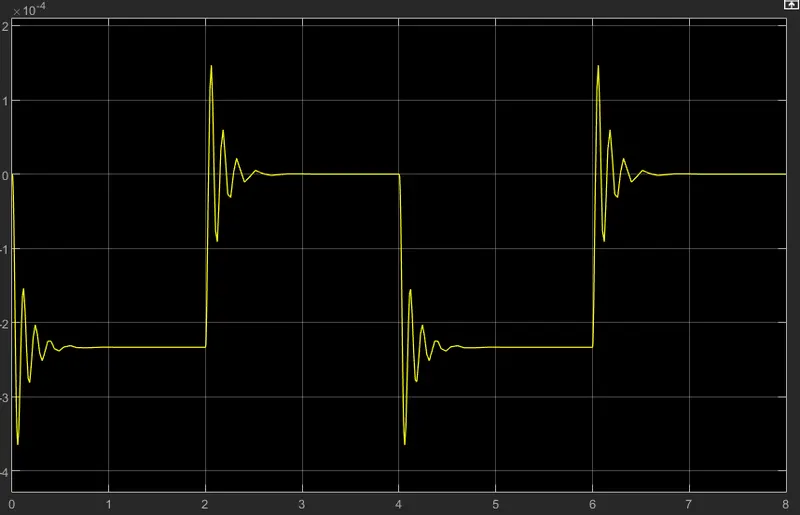
4. The magnetic filed from the solenoid results in force that moves the plunger which is then monitored by the IDEAL TRANSLATIONAL MOTION SENSOR BLOCK and can be visualized in the SCOPE1 BLOCK.
5. A SWITCH BLOCK is connected to the BATTERY BLOCK and only when the switch is closed, the input signal flows through the solenoid.
6. A SOLVER CONFIGURATION BLOCK and ELECTRICLAL REFERENCE BLOCK is attached to the electrical block diagram which consists of pulse generator, switch, battery and solenoid.
7. A MECHANICAL REFERENCE BLOCK is attached to the other part of the solenoid as the plunger movement comes under mechanical motion.
SIMULINK BLOCK:
RESULTS:
PLUNGER MOVEMENT:
CONCLUSION:
The plunger position observed has a continuous depleting sine wave form in a Pulse signal as the damping paramaters are included.
THERMISTOR ASSIGNMENT
PROCEDURE:
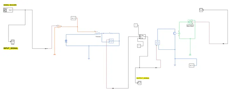
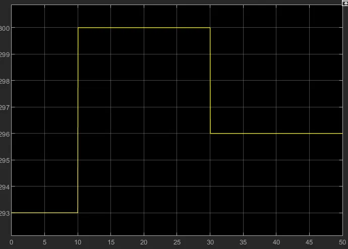
1. A SIGNAL BUILDER BLOCK is created to create input signal which has the following conditions:
293 K from 0 to 10 seconds and 300 K from 10 to 30 seconds and 296K from 30 to 50 seconds.
2. A SCOPEBLOCK is connected to the signal builder block to check the input signal.
3. A Simulink-PS CONVERTER BLOCK is connected to convert the simulink data to Physical signal data.
4. The physical signal is then transferred to the CONTROLLED TEMPERATURE SOURCE BLOCK.
5. The temperature data is fed to the NTC thermistor. In NTC thermistor, resistance decreases as the temperature increases and has various applications.
6. A RESISTOR BLOCK is connected to the BATTERY BLOCK and VOLTAGE SENSOR BLOCK is also connected to the RESISTOR BLOCK to monitor the resistance of the resistor with change in temperature.
7. A fan is modelled as a DC MOTOR BLOCK and a DC CURRENT SOURCE BLOCK is connected with it.
8. 2 SOLVER CONFIGURATIO BLOCKS are created and connected to the Thermistor side and DC motor side.
9. A MECHANICAL ROTATIONAL REFERENCE BLOCK is connected to the motor side, THERMAL REFERENCE BLOCK is connected to the temperature blocks side and a ELECTRICAL REFERENCE BLOCK is connected to the battery side.
BLOCK DIAGRAM:
INPUT SIGNAL (TEMPERATURE DATA)
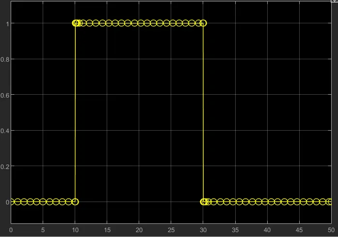
OUTPUT SIGNAL (FAN SWITCH ON AND OFF )
CONCLUSION:
The results clearly shows that when the input temperature is less than 298 K from 0 to 10 seconds and 30 to 50 seconds, the fan is switched off and when the temperature is more than 298K for 10 to 30 seconds, the fan is switched ON