Week - 4
AIM
Q1
To implement the control logic of a “washing machine” using Stateflow as per given sequence:
- If the power supply is available, the system gets activated
- If the Water supply is not available, stop the process & indicate through LED
- Soaking time should be 200s followed by Washing time of 100s
- Then rinsing happens for next 20s & dryer runs for 50s and after completion, turn on the finished LED
THEORY & STEPS
- Since the working of washing machine involves various states, "State flow" control logic tool is used to analyse the given conditions. "Stateflow" is used to model reactive systems via "state machines" and "flowcharts" within a simulation model. State flow diagram is drawn using "chart" in simulink model.
- Power supply and water supply are the inputs to the chart.The outputs are lamps for power, water, soak, wash,rinse,dry and process completion.
- In order to indicate every step of the washing process, each lamp is named by the corresponding process. Red colour indicates OFF state and green colour indicates ON state of the lamp.
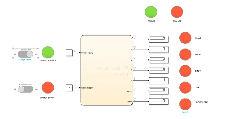
- When power supply is ON and water supply is OFF the corresponding lamp of water turns red and hence further washing process does not occur.
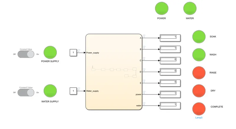
- When both power and water supply are available, the entire washing process take place step by step. When the entire process is completed, the process completion lamp turns ON.
Simulation link https://drive.google.com/file/d/1qgtryR77zSfnJQLMxPIZAIiCLSTQJWyg/view?usp=sharing
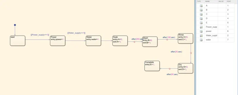
The state flow diagram and process for each case is shown below:
The chart modelled is given here. The inputs and outputs are shown in the symbols pane on the right side.
Output when power supply is ON and water supply is OFF:
Output when both power supply is ON and water supply is ON and washing process is going on:
Output when the entire process is finished:
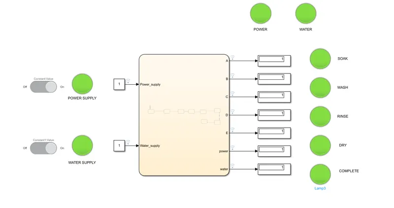
Thus the control logic of washing machine using Stateflow is implemented.
Q2
AIM
To make a Simulink chart for the “Gear shift” logic as per below conditions and to give speed input while the simulation is running & display the gear number.
Speed Range(kmph) Gear
0 to 15 1
16 to 25 2
26 to 40 3
41 to 60 4
Above 61 5
THEORY & STEPS
We all know that shifting between the gears is required for smooth driving of the vehicle. Internal-combustion engines run at high speeds, so a change in gear is necessary to transmit power to the drive wheels, which turn much more slowly.The gearbox provides a selection of gears for different driving conditions: standing start, climbing a hill, or cruising on level surfaces. The lower the gear, the slower the road wheels turn in relation to the engine speed.The gearbox is the second stage in the transmission system, after the clutch . It is usually bolted to the rear of the engine, with the clutch between them.Modern cars with manual transmissions have four or five forward speeds and one reverse, as well as a neutral position.The gear lever, operated by the driver, is connected to a series of selector rods in the top or side of the gearbox. The selector rods lie parallel with shafts carrying the gears.
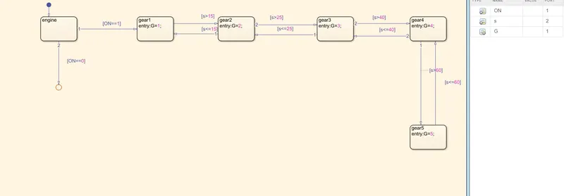
- State flow diagram is drawn using 'chart'. The speed conditions and corresponding gear numbers are specified for each block in the chart.
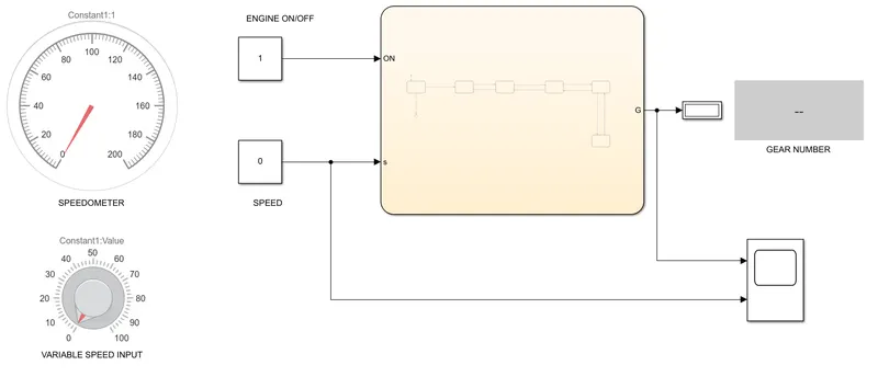
- Input speed is varied during simulation using a knob (variable speed input).
- Speedometer indicates the given speed.
- If the Engine is ON and an input speed is given, corresponding gear number is obtained as output in the display.
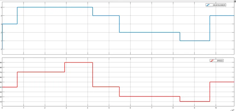
- The plots are given below from which it is evident that gear shift occurs according to the specified speed range in the question.
Simulation link https://drive.google.com/file/d/18c9bOXyFjhsdtdfrwrLtzGtYHiLa-5Z3/view?usp=sharing
Chart for gear shift logic: (Here, engine ON/OFF and speed 's' are inputs and gear number G is the output)
The complete Simulink model diagram is shown below:
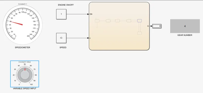
When speed is 50kmph, the gear number is "4" (41 to 60kmph : gear4)
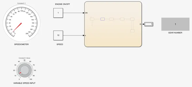
When speed is 10kmph, the gear number is "1" (0 to 15kmph : gear1)
Speed is changed at various instances during simulation and the gear shift is plotted along with the speed changes in the scope.
Thus gear shift logic is successfully implemented using Simulink.