Week -2
1.SIMULINK MODEL OF DOORBELL
AIM
1.To make a Simulink model of doorbell using solenoid block and observe the physical movement of the plunger when the switch is closed for 2 seconds and then released.
THEORY
The electric bell consists of a simple circuit of which an electromagnet is the main part along with armature, spring, armature rod, hammer and a gong. The figure below shows the internal mechanism of an electric bell.
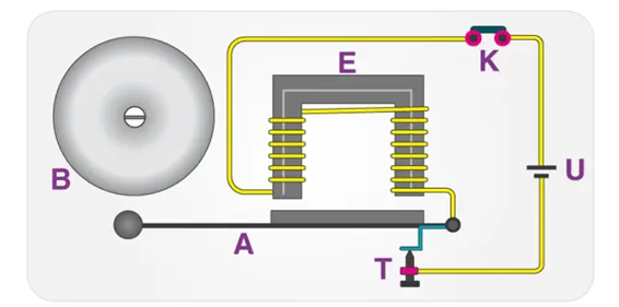
When the switch is pressed, the circuit is complete which causes the current to flow and the electromagnet generates a magnetic field that attracts the iron strip towards it and hence the striker strikes the bell.
Magnetic Field in a Solenoid
A solenoid is a type of electromagnet which produces a controlled magnetic field.
The formula for the magnetic field of a solenoid is given by,
B = μoIN / L
where,
μo=Permeability of free space
N = number of turns in the solenoid
I = current in the coil
L = length of the coil.
STEPS
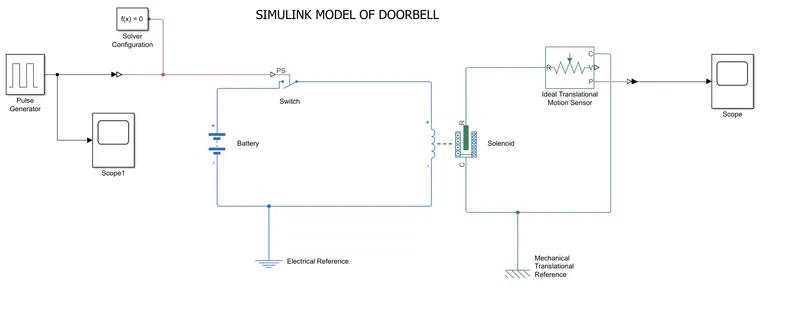
1.The doorbell circuit is set up using battery, switch, solenoid, pulse generator and an ideal translational motion sensor (for sensing the plunger movement).
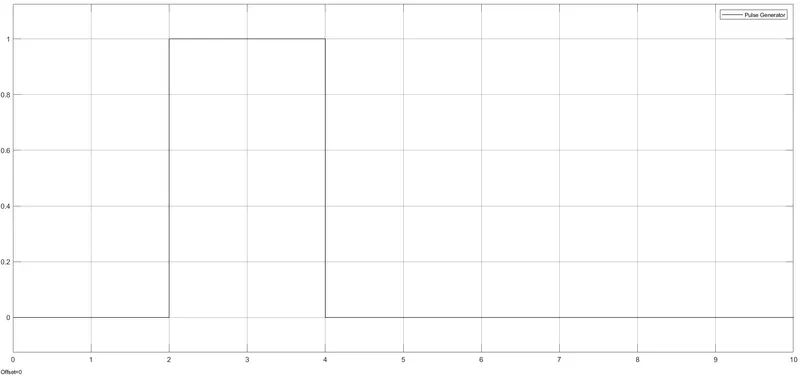
2.A signal of Amp=1, Period=10secs, Pulse width=2secs, Phase delay=2secs is given as input. When the external input signal to the switch is greater than the threshold value the switch is closed otherwise the switch is open.
3.The switch is closed for 2 seconds and then released. The motion of the plunger is obtained in the scope. The stroke for zero spring force is 5mm. When the switch is closed, the plunger moves towards the core which causes ringing of the bell.
Simulation link https://drive.google.com/file/d/14hMsqxoTRxhwxic80gXi8IDshd-2Y8uZ/view?usp=sharing
RESULTS
a)Input waveform (switch ON for 2sec and then released) is shown here
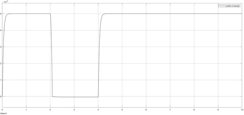
b) At 2sec,when the switch is ON, the plunger which is at 5mm, moves towards the core causing the bell to ring and after 2sec, it returns back to the normal position.(damping = 10N/(m/s))
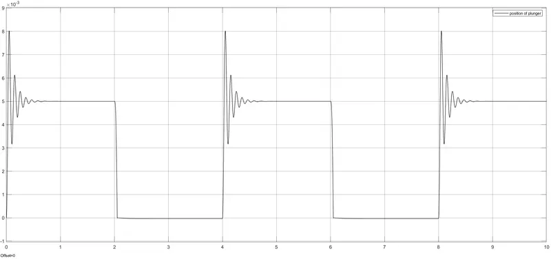
c) When damping= 1N/(m/s) and signal of Amp=1, Period=4secs, Pulse width=2secs, Phase delay=2secs is given as input, it is found that after ringing the bell, the plunger returns back with more oscillations compared to the above case.
2.FAN ON OFF CONTROL
AIM
To make a Simulink model of a system containing a thermistor to sense the temperature of a heater and turn on and off the fan as per the given condition.
THEORY
Thermistors are a type of variable resistor which notices the change in temperature and are used when a precise temperature reading is required. The resistance of a thermistor is inversely proportional to the temperature.
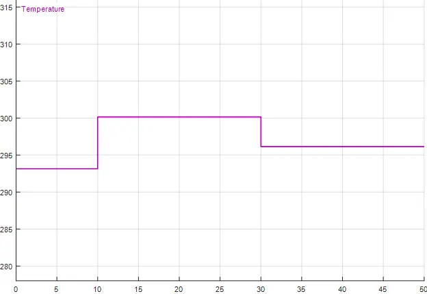
A signal builder block is used to create the required input temperature conditions.
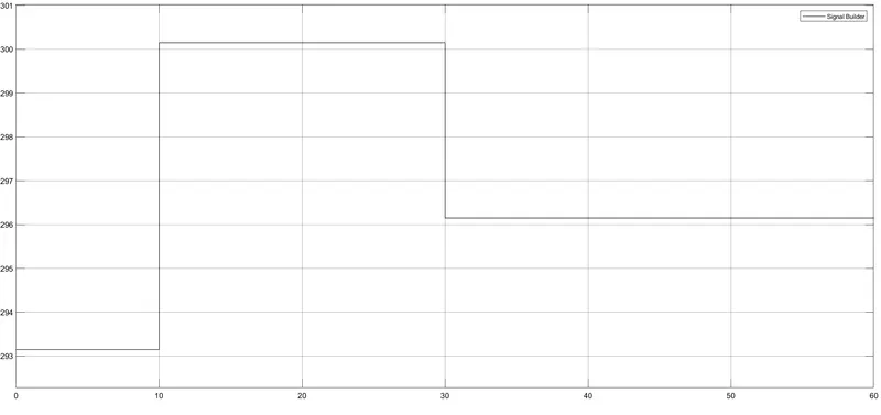
200 C (293.15K) from 0 to 10sec
270 C (300.15K) from 10 to 30sec
230 C (296.15K) from 30 to 50sec
The signal plot is shown here, where the temperature is in Kelvin.
STEPS
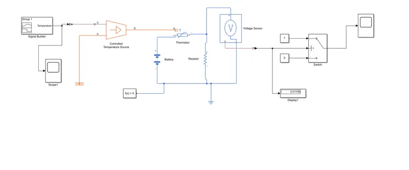
The temperature variations are fed to a controlled temperature source (which maintains a controlled temperature difference regardless of the heat flow rate) and is sensed by a thermistor. The other main components of the model are battery, thermistor and a resistor. A voltage sensor is connected across the resistor to sense the voltage drop value and this value is used as threshold for the operation of the fan. (fan is represented here by a switch) ie; when the temperature goes above 250 C, the switch is closed and the fan is turned on.
The simulink model diagram is shown below:
Simulation link https://drive.google.com/file/d/1xhhk-sWL2FDBBX21vZz_Vuy0ZAGlhM90/view?usp=sharing
RESULTS
The temperatures during different time intervals is shown in the diagram here.
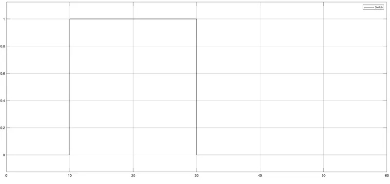
From the graph below, it is evident that from 0 to 10sec, the fan is OFF as the temperature is only 200 C, whereas the fan is 0N from 10 to 30sec as temperature is greater than 250 C and from 30 to 50sec, again the fan is OFF as temperature drops down to 230 C .Thus the required operation of the fan is obtained.