Week 4 - 2D Meshing for Sheet Metal
AIM
To create mesh for the given component – Cross Car Bar (CCB) as per the given mesh parameters and quality criteria. Assigning thickness to the meshed component.
GIVEN
- Model in .iges format.
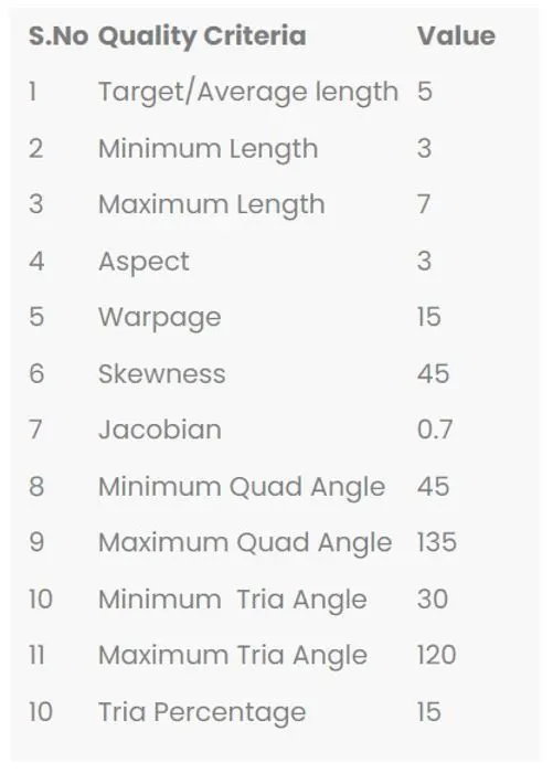
- Quality Criteria for the Shell Mesh:
OBJECTIVES
- To generate mid-surface for the various parts of the given CCB assembly.
- To mesh each part with the given mesh parameter and make them to conform to the quality criteria.
- Draw shell as solid
METHODOLOGY/PROCEDURE
Generic procedure for working out the connections on the given rear side door model is shown below:
1. Import the geometry:
The given .iges model file will be imported into ANSA in this process. Analysis of the given FE component – for getting start with geometry cleanup in a very effective way.
2. Assigning Perimeter:
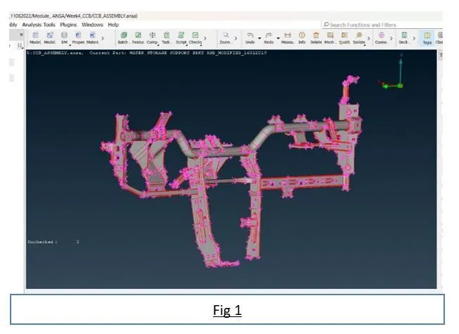
Inspection of surfaces is one of the criteria under geometry checks. Surface inspection is carried out to figure out whether the surfaces are out of any irregularity and non-uniformity. Irregularities in the surfaces can be spotted with ease by smoothening the surfaces. This can be done either by length perimeter = 1mm or by fine tool. Former method of assigning length perimeter = 1mm is done in the given case as shown in fig (2), and the surfaces are inspected. The command for assigning perimeter and macros length can be accessed by Mesh ----> Perimeters ----> Length ----> Perimeter/Macro = 1mm.
3. Topo:
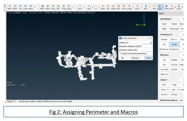
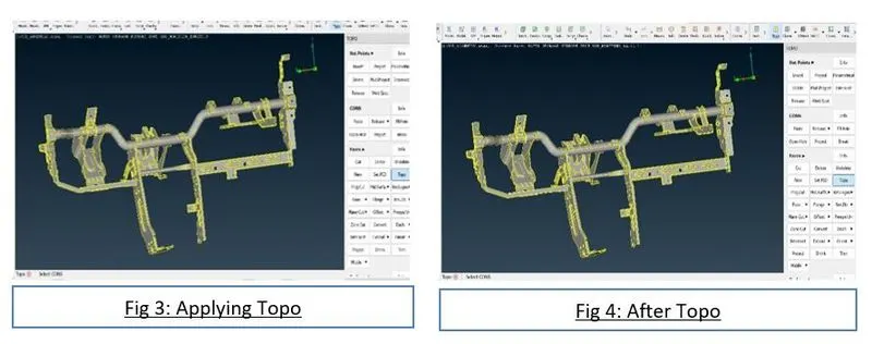
Topology should be done in-order to stitch the surfaces together. Topo command can be accessed in Topo deck ----> Faces ----> Topo.
4. Geometrical Checks:
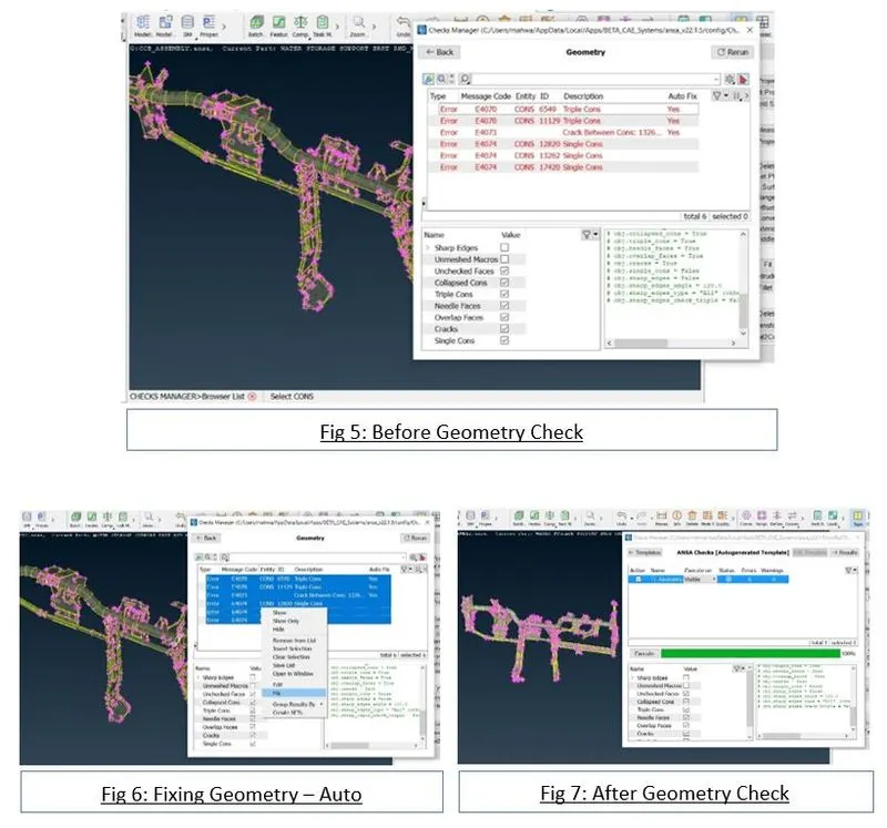
Geometrical checks is carried out to the given component. Ansa has integrated geometrical check tool to inspect surfaces. Checking of geometry is carried out to ensure that the given surfaces of the component are out of geometrical errors in the form of extra surfaces, triple cons, needle edges or faces, etc. If error found, it can be fixed by either auto fix option in the ANSA or by manual methods. Geometry check command can be accessed in Tool bar ----> Checkup ----> Geometry. The component after assigning perimeter and carrying out geometry checkup are shown in Fig (5) to Fig (7).
5. Thickness measurement:
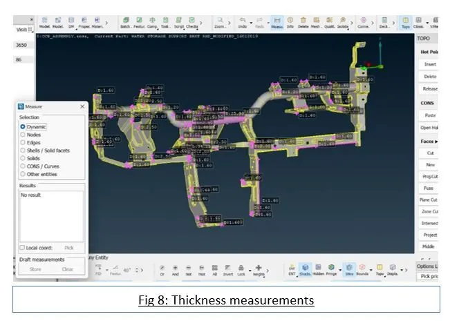
The thickness should be measured throughout the critical areas of the components as per the geometry demand. The command can be accessed in Utilities bar ----> measure. It is up to the engineer’s discretion to measure the thickness with the node or cons or faces options as per the component demands. The components with measured thickness are shown below:
6. Mid-Surfacing:
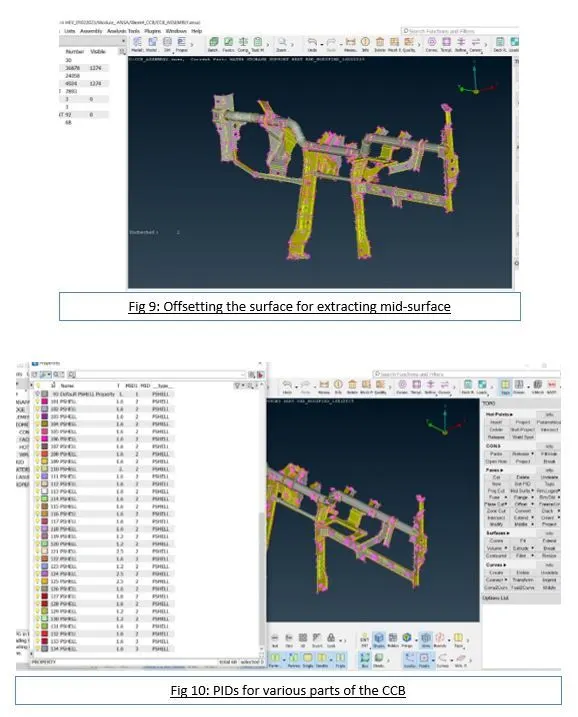
Mid-surfacing is the process of extracting mid surface of the above component in order to simplify the geometry, while entering the thickness manually. This can be accessed by Topo ----> Faces ----> Offset ---->(either a specific face can be selected or window selection can be done depending on the geometry of the component). And thickness need to be entered manually in the offset window. Property Identity(PID) need to manually set in the case of Offset. PID can be accessed by Topo ----> Faces ----> Set PID.
While, later can be accessed by Topo ----> Faces ----> Mid Surf. In this case, thickness and property will be calculated automatically by ANSA and mid-surface will be formed. Either Boolean operations need to be carried out to access the formed mid-surface or just by toggling the properties in the property manager, one can access the mid surface. Care should be taken to ensure whether the material defined or not in the material identity(MID) manager located in the “Lists” adjacent to PID.
The mid-surfacing of the CCB assembly by offsetting is shown Fig (9); and the set of PIDs that are assigned to the various parts of the same is shown in Fig (10) – as highlighted.
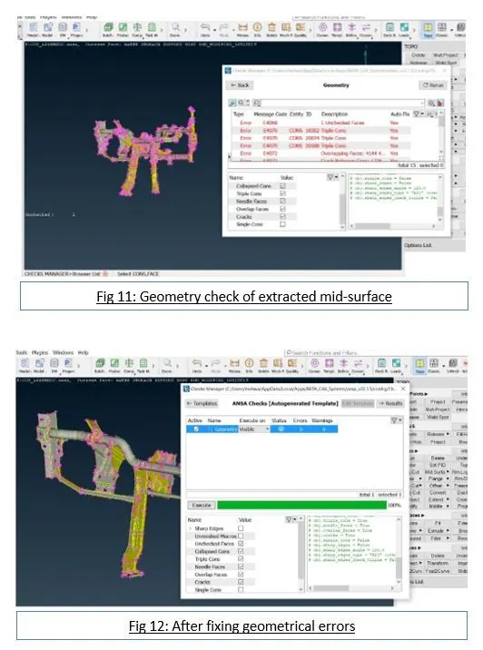
Geometry check should be carried out again in order to make sure extracted surface is out of any geometrical errors. Geometrical errors detected while checking as shown in Fig (11) and the same are rectified by manual methods; and the resultant mid-surface without any geometrical errors is shown in Fig (12).
7. Assigning Mesh parameters and Quality Criteria:
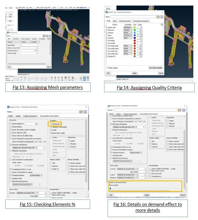
Assigning of mesh parameters and quality criterial carried out as shown in Fig (13) and Fig (14).
8. Meshing:
Switch to Mesh deck. Set the length of perimeter and macros to 5. This command can be accessed and executed as follows: Mesh ----> Perimeters ----> Length. After assigning length, the any hole feature needs to be appropriately matched with the nearby edges in order to get a smooth mesh flow. This can be carried out by Slide and Mark/Unmark tool as shown in Fig 15. This command can be accessed and executed as follows: Mesh ----> Perimeters ----> Slide; and Mesh ----> Hot Points ----> Mark/Unmark. Since this is CCB assembly, discretion has been considered to spot out the hole is for fasteners equipped with washer or not. Few fastener hole has been treated with fastener in the form of ‘Zone cut’. This zone cut tool can be accessed in both Topo and Mesh decks. In Topo deck, zone cut can be accessed by Topo ----> faces ----> Zone cut ----> Selection of hole perimeter. In Mesh deck, zone cut can be accessed by Mesh ----> Shell Mesh ----> Zone cut ----> Selection of hole perimeter. In both the cases, zone width should be assigned. This zone width depends upon the minimum and maximum length, and in case zone cut width is assigned as 3.1 Units. And in the latter case of assigning zone cut with mesh deck, washer edges are converted to perimeter with ‘Edge2Perimeter’ command under perimeters and frozen to get rid of any nodal disturbances during working out with mesh flow.
After completing all the preliminary assigning work, it is time for meshing the component. Mesh can be done by multiple tools in ANSA. ‘Best and Spot mesh’ are used in order to achieve better results. The command can be accessed by Mesh ----> Mesh Generation ----> Spot Mesh/Best. ENT and PID(reg) can be switched over for optimal meshing.
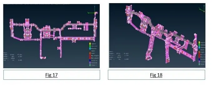
The mesh generated can be improved by Reconstruction tool or Improve tools. Former can be accessed by Mesh ----> Shell Mesh ----> Reconstruct(Window Select). Whereas the latter tool has additional improvement features to offer viz., reconstruct, improve, reshape and fix quality. As per the requirement, user can utilize improve tool. To access this tool: Mesh ----> Shell Mesh ----> Improve(Window Select). Make sure that meshed components should not consists of any Offs. Whenever it is demanding use split option to split up mesh grid or to join the grid to nullify quality or to improve mesh. Split is a hybrid command which is located in: Mesh ----> Elements ----> Split. On the left-click of mouse button, it splits the element with respect to Edges or Nodes or with both as per the user choice. Upon right-click, it works as join or swapping of edges. Trias at the edge or at the perimeters should be avoided in order to reduce the stress concentration. Rotating quads and opposite trias should be avoided as well in order to get better results. Meshed component is shown in Fig 17 and 18.
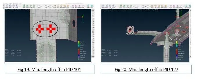
Apparently, there are 11 off elements that are failing for ‘Minimum length’ quality criteria should is completely unavoidable, and is highlighted in the Fig 19 and 20.
9. Assigning Thickness:
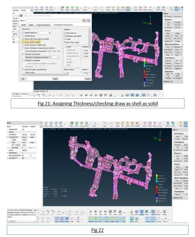
Thickness is assigned to all the components of the CCB by checking the ‘draw shell as solid’ under presentation parameters in Quality Criteria as shown in Fig 19. The resultant solid shell model is in Fig 20.
10. CONCLUSION
Hence, the given CCB assembly parts are meshed as per the given quality criteria using manual mid-surfacing method. The thickness is assigned to the meshed component and graphically represented as draw shell as solids.