Week 4 - 2D Meshing for Sheet Metal
the given sheet meta model is already submitted to Mr. David in FEA Super course for jan enrollments. please consider this ....
the same sheet metal model is attached in the submission attachement.
Sheetmetal part 2
Aim: To mesh the given model using the method of manual mid surfacing.
Procedure:
- Visual inspection: it is the very first procedure to follow after importing the geometry and before mid-surfacing or meshing.
- After importing the model into the software change the element size of the model to 1mm initially form the option Perimeter> Length, for both perimeter and macros in the mesh module.
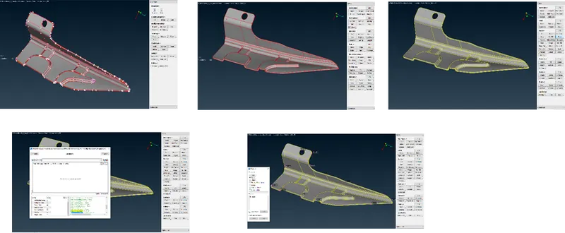
- In the geometry we can see the red color unconnected line and those need to be connected with each other before proceeding. This can be done by using the Faces> TOPO in the TOPO Module. Select the whole geometry and accept to see all the red lines connected with each other forming the Yellow lines.
- After connecting the lines, check for the geometrical errors. Go to check > Geometry after selecting all the error names in the list click Execute> Show results.
- When there are no possible errors left in the list we can move forward and go with measuring the geometrical thickness. We can see the thickness all side is 1.5mm uniformly.
- Mid surfacing through manual method can be opted for mid-surface generation.
- Mid-Surfacing:
- For Mid-surfacing through manual method, we can opt. for Faces > Offset.
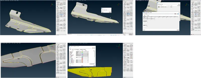
- Select the region required to offset by using Feature line selection and accept the selection. To create a mid surface, input the offset distance of 1.5/2 mm. For direction of Offset use the negative (-ve) sign for opposite direction offset. In option list select the ask always option and create new property in property manager tab for mis surface.
- Clean the mid surface for any goemetrical errors. Using Faces > Cut and Faces > join option toggle or create the lines on surfaces to match the minimum length requirements. Use the Topo options to join stitch or connect the lines to one another.
- If using Curves > Create. We shold project the the curve on the surface in order to stich the curve with the surface.
- Set the mesh parameters in the dialogue box and set the characteristic length as specified using the Perimeter> Length.
- Meshing:
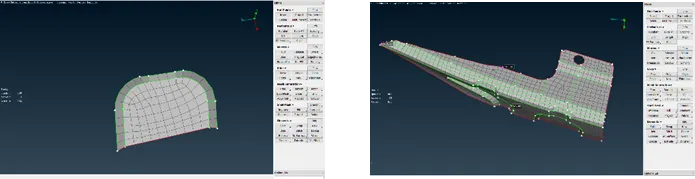
- Using the option of Mesh generation > Spot mesh select the region reuired for meshing and create the meshes.
- Using the Elements > Split command correct the mesh flow as required to satisfy the quality criterias and follow the thumb rules of creating the mesh flow.
Conclusion:
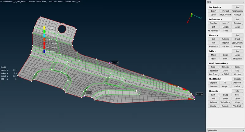
The Practice model for Sheetmetal Part no 2 was completed with 8 elemental failures whichfail for elements which are present in the corners which are un-evitable. Succesfully all the major points are taken care while meshing the Mid-surface.
After completeing the model the mesh flow looks something like this.
Thank you