2D meshing for Plastic components
Objective:-
- 2D meshing for Plastic components
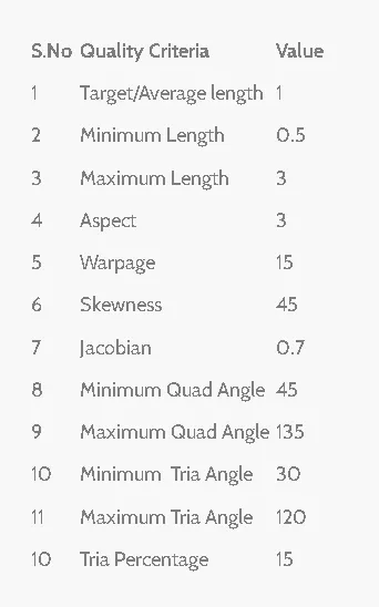
- Plastic Bottle Cap model, check for the geometrical errors and take the mid surface by suitable mid surfacing techniques. PID and Thickness assignment has to be done for all the mid surfaces. Mesh the same with given element Quality criteria.
Theory:-
ANSA which stands for Automatic Net generation for Structural Analysis is one of the popular commercial software using in the CAE field for both FEA and CFD analysis. It was developed by Beta CAE Systems and was initially built as a mesh generation tool specifically for structural analysis (hence the term Net generation for Structural analysis) but then later was made compatible with other sub-domains including Computational Fluid Dynamics.
The two main flagship products developed by the BETA CAE are the ANSA pre-processor and the µETA post-processor, both widely preferred in various domains including automotive, railway vehicles, aerospace, motorsports, chemical processes engineering, energy, electronics, heavy machinery, power tools, and biomedical
ANSA being a multidisciplinary CAE dedicated pre-processor, unlike most other commercial FEA software, primarily focuses on the pre-processing of CAD geometry, from CAD model build-up to ready-to-run solver input file, in a single integrated environment for numerous analysis codes. Furthermore, its functionality spans from data translators, clean up and assembly to batch meshing, model completion, check, and solution scenario definition
The coloring has to do with the connectivity of the
Faces.
Red: a SINGLE free edge CONS
Yellow: a DOUBLE CONS shared by two
neighboring connected Faces
Cyan: a TRIPLE CONS shared by three or more
connected Faces
You can activate and deactivate the visibility of each of the three types of CONS separately using the SINGLE, DOUBLE, and TRIPLE flag buttons.
De-activating here the DOUBLE flag shows only the free red and triple cyan CONS. Apart from the free edges of the sheet metal, there are other openings (gaps, untrimmed Faces, etc.) that must be corrected.
Solution Procedure:-
Bottlecap is plastic components which have varied thickness throughout
Step 1:-
- Read the CAD file Perform the topology using the topo option.
Step 2:-
- Perform the geometry cleanup and check the geometry.
Step 3:-
- Measurement and assessment of the thickness of different components were done.
Step 4:-
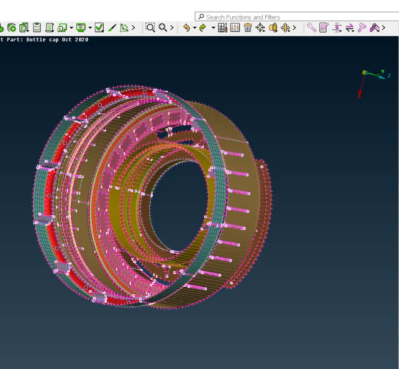
- Extraction of the mid surface was done using the offset and middle command and properties were assigned.
Step 5:-
- Perform the Mesh generation by using different commands was done.
Step 6:-
- A quality check was performed within assigned parameters and resolved using different tools.
Step 7:-
- The shell geometry was converted into solid geometry
_____________________________________________________________________________________________________
Topology and Geometry Cleanup:-
Importing CAD - The CAD geometry designed by a CAD/Design engineer can be imported into the ANSA software either as a .step or as a .iges format. These are the most popular CAD formats that ANSA recognizes.
It is recommended to set a specific limit on tolerance and resolution prior to importing the CAD.
There is a high chance that the imported CAD may face having some errors. These errors may include orientation issues, duplicate or missing surfaces, sharp edges (which could cause errors while meshing), etc. Initially, every model has to be checked for geometrical errors. Prior to this, it is best practice to perform a topology clear-up to make sure that continuity is maintained between every cons and that it doesn't display double cons as single cons.
This topology cleanup is performed on the model using the topo operation in the FACES block of the TOPO module.
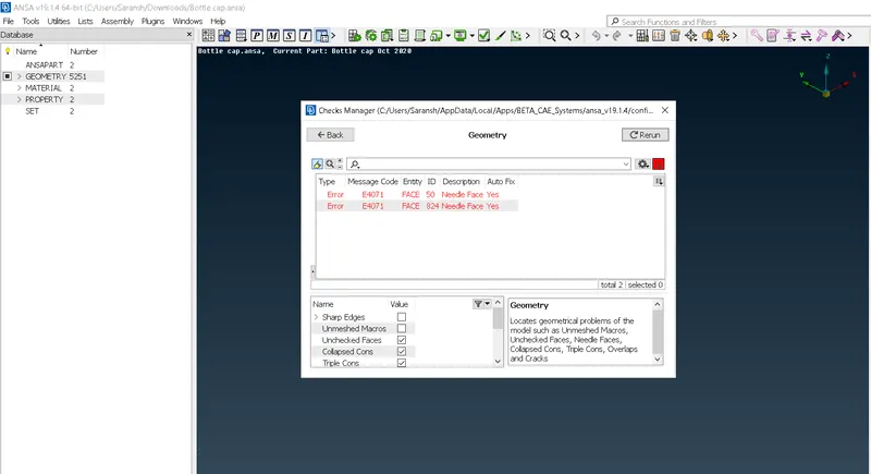
ANSA can give a layout of all the geometrical errors from our component model.
- A target length (say 5mm) is set for the entire model in both the perimeter and the macro-region.
- Perform a topology cleanup using the Faces-> Topo.
- Do a geometry check for single, double, and triple cons and eliminate those that may cause geometrical errors.
In case the disorientation of cons is moderate then the ANSA Autofix option could eliminate certain errors. ANSA is also capable of clearing small geometrical errors if it's within its capability and based on the hardware memory allocated for it.
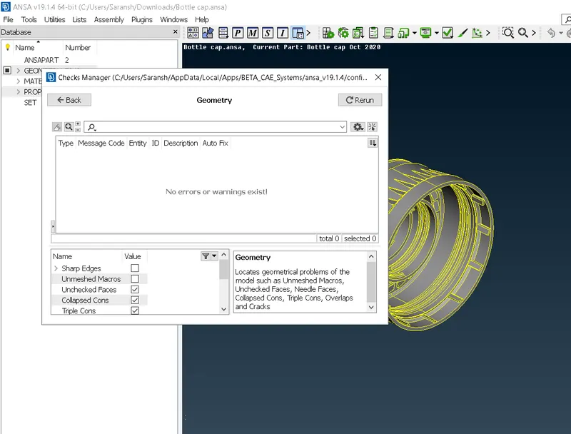
Finally, the model is checked for geometrical errors in the check manager. If any errors in triple/single cons arise, ANSA in most cases would be able to clear it using the FIX command. IF the model passes for topology cleanup the following image is displayed.
To perform geometric checks, Checks - Geometry - Select required params
After Geometry cleanup performance:-
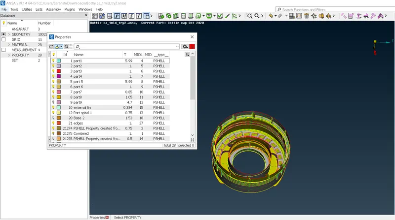
As for the plastic components, there is a variation in the thickness:-
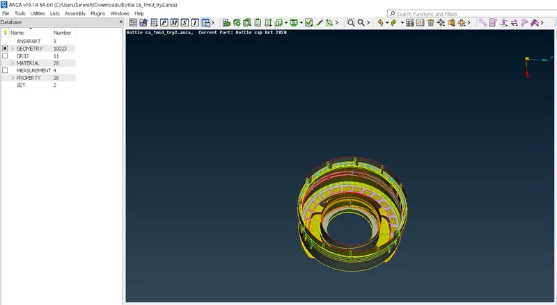
Different PID is set for different components with varied thickness:-
_____________________________________________________________________________________________________
______________________________________________________________________________________________________
MID SURFACE EXTRACTION
Mid surface extraction is usually used for sheet metal components where the thickness of the component is negligible compared to the other two dimensions. Mid-surfaces can be extracted in ANSA either automatically or manually. In certain cases, ANSA may fail to deliver the proper FE model, in the case of auto mid-surface extraction, if the model comprises critical regions with complicated features or most small features. Another reason why an auto mid-surface feature may fail is because of varying thickness across the model.
Mid surface extraction depends on the symmetry and thickness of each respective part in a component. In the case of varying thickness, the auto mid surface (Topo - Faces - Mid surface - skin, casting, etc..) doesn't give a proper result. Hence manual mid-surface extraction using the offset and manual mid features can be implemented.
The offset command (Topo - Faces - Offset) can be used for known thickness features in the component where discontinuity occurs due to other mid features present. Whereas the single/multi middle feature (Topo - Faces - Middle) can be used for features that are symmetric and are separate from the rest of the component
________________________________________________________________________________________________________________
MESHING:-
Meshing is a very integral part to construct the Finite element model. Meshing is the process of discretization of the CAD model into a so-called 'Finite-Element model or FE model'. Meshing is one of the core processes which makes the Finite element method possible, as it helps us convert a continuous problem with an infinite number of points into a discrete set of elements which then can be computed for the field variable and integrated over the whole domain.
A well-structured mesh affects the accuracy of your result, computational time, convergence. While a lot of commercial pre-processing and solver bundled CAE software packages do allow the users to tweak the type of mesh they require, yet they are limited. While a few others (like ANSA and HYPER MESH) are more flexible than they allow users to fully customize their meshed FE model while mitigating errors through a clean GUI.
structured mesh affects the accuracy of your result, computational time, convergence. While a lot of commercial pre-processing and solver bundled CAE software packages do allow the users to tweak the type of mesh they require, yet they are limited. While a few others (like ANSA and HYPER MESH) are more flexible than they allow users to fully customize their meshed FE model while mitigating errors through a clean GUI.
________________________________________________________________________________________________________________
MESH PARAMETERS AND QUALITY CRITERIA
Prior to meshing the user has to define the required mesh parameters. ANSA tries to follow this input data to give a more precise mesh. In the mesh parameter popup box, the average length of each mesh element is specified along with the limits (i.e min and max target length).
Moreover, the type of mesh element (quad/tria) and the element order (1st/2nd order) can also be defined in the parameters tab. This can also be changed during any mesh generation command or even during the mesh refinement process.
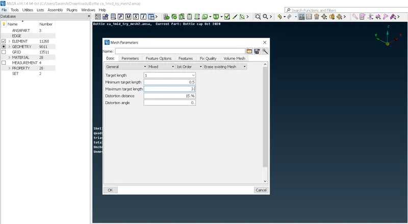
However, in some cases, these mesh characteristics of the generated mesh may deviate from the user-defined parameters. Hence, to obtain a more accurate mesh we set up the quality criteria to check for those elements that fail the defined parameters.
These failing elements can then be reconstructed using ANSA's efficient mesh refinement algorithms in the MESH module (MESH - Shell Mesh - Reconstruct)
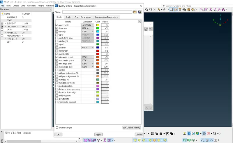
QUALITY CHECKS
The quality checks used for 2D surface mesh-like trias and quads.
- ASPECT RATIO
This computes the ratio of the longest edge of an element (single element) to the shortest edge of the same element.
In most cases, it is preferable to have an aspect ratio of 3 or 5. Meaning a ratio of 5:1 such that the longest side of an element doesn't cross more than 5x times that of the smallest side of the same element.
The formula to compute the aspect ratio varies for each element. For example, the aspect ratio of a 2D tria element is calculated as 2Ri/Ro, where Ri is the radius of the circle inscribed in the tria element and Ro is the radius of the circle circumscribed outside the ends of the same element. Similarly, the a.r of a 3D tetrahedron would be 3Ri/Ro, where Ri and Ro represent the same exact parameters.
An aspect ratio of 1 seems to be the most ideal. However, it cannot be achieved at each and every element. For example, the ideal aspect ratio for a tria (considering an equilateral triangle) should be 1.
- WARPAGE
It is the amount by which a mesh element or the element face deviates from being planar.
For example, in the case of a quad, it can be calculated by splitting up it into two trias by constructing a diagonal between two opposite sides and finding the angle between these two tria planes.
This quality criterion pertains to only quad elements with an element of warpage of 0 indicates it being perfectly planar.
- SKEWNESS
Skewness measures the angular deviation of the element from, as usual, being ideal. This parameter can be used to measure both tria and quad shell elements.
For example, in a tria, it is calculated by finding the minimum angle between the vector from each node to the opposite mid-side AND another vector lying between two adjacent mid sides at each node of the element as shown below.
Similarly, skew in quads are calculated by the angle formed between 2 lines joining the opposite mid-sides of a single element
By default most pre-processors check for skew value above 0.5. However, when these elements are used to map or capture intricate features or small fillets, then these elements would probably fail for the criteria
- JACOBIAN
This is a scale factor arising due to the transformation of the coordinate system i.e from the global coordinate to the local coordinate. It checks for deviation of the element from being perfect or ideal. It is calculated by mapping the element from its parametric coordinate onto its global coordinate.
The ideal jacobian value of an element would be 1 while any value greater than 0.6 is still acceptable.
- TAPER
The feature like a few others only checks a quadrilateral element.
It is determined by finding the area of the triangle formed from each corner points in a quad element as shown below.
- CHORDAL DEVIATION
It checks the quality of how well curvatures like fillets, holes are modeled.
It is calculated by the distance between the mid node to the curved surface of an element.
Mesh quality parameters
Meshing is the process of discretization of the CAD model into a so-called 'Finite-Element model or FE model'. Meshing is one of the core processes which makes the Finite element method possible, as it helps us convert a continuous problem with an infinite number of points into a discrete set of elements which then can be computed for the field variable and integrated over the whole domain.
- To obtain the ideal shape of the 2D,3D mesh element. For example, the ideal shape of a tria is an equilateral triangle or a quad as an ideal quadrilateral.
- To control the mesh element type. While having a mix of trias and quads are the most optimal way, the increase in the number of trias more than or over a certain percent of quads is not appreciable. Trias does provide a good smooth mesh flow transition, however, trias at certain places are unendurable by certain commercial software.
- Control warping or out-of-plane shifting of elements i.e control distortion
- Complex geometries generate the most intolerable mesh elements. Intricate and small features can only be captured using certain elements and these elements may also be prone to distortion hence would not be really able to capture these components.
- Solver capability. While most solvers can handle any distorted or deformed mesh element, in most cases, they just skip through them, or the approximation at that element may not be the ideal one.
- Inaccuracy. Much similar to the above point made, certain elements like trias at certain places like edges of a mid-surfaced plane or at hollow edges of a hole may not give you the desired results.
- Convergence. mesh elements that fail at certain quality check parameters like aspect ratio would fail to converge during solver runtime.
________________________________________________________________________________________________________________
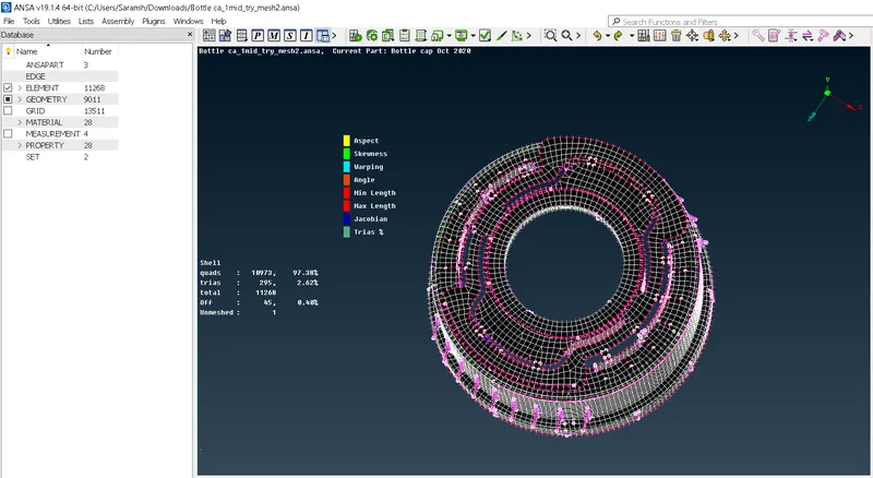
Meshing:-
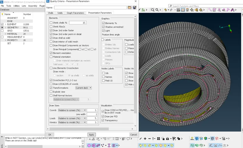
- Draw shell as solid:-
_______________________________________________________________________________________________________________
Learning:-
- There were many errors faced during meshing and many times mid surface generation was done and deleted and redone.
- Mid surface extraction for different thicknesses as in this bottle cap was a time taking process and took a lot of time
- After mid-surface extraction performing meshing was a hard task, many times meshing was with a lot of OFF elements, and performing the quality criteria was a great task to learn different aspects of meshing.
- Performing meshing for different parts also made great advancements in learning new concepts of this preprocessor.
Conclusion:-
- Geometry cleanup was performed.
- Thickness measurement was performed.
- Mid surface extraction was done by using the middle and offset option
- Meshing was performed with the use of different tools.
- A quality criteria check was performed and removal of off elements was done.
- Shell geometry was converted into solid geometry.
References:-
https://enterfinite.com/blog/f/a-beginners-guide-to-mesh-generation-using-ansa?blogcategory=General