Week - 4 - 2D meshing for Plastic components
2D MESHING FOR PLASTIC COMPONENT
AIM:
To Generate the mid surface for all the components after checking the geometrical errors and mesh the mid surface with the given element Quality criteria
GIVEN:
CAD MODEL:
BOTTLE CAP
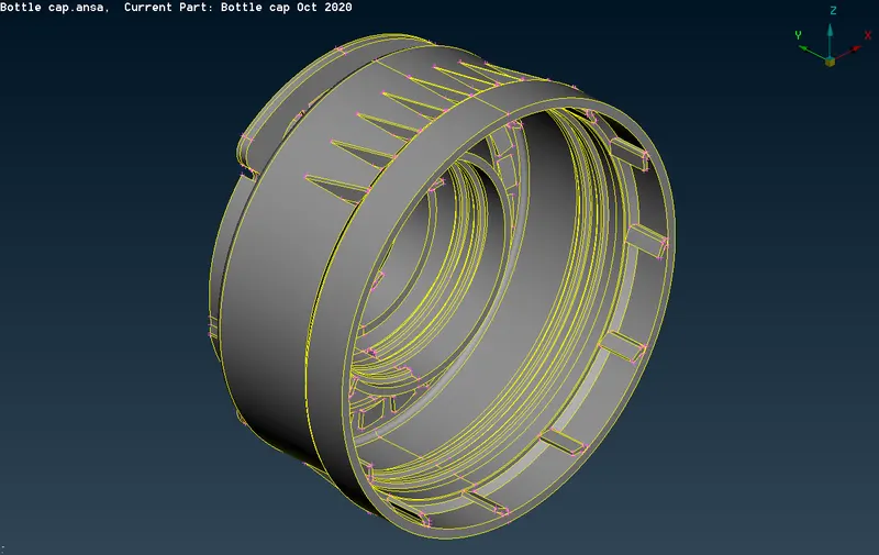
QUALITY PARAMETERS:
|
S.No |
Quality Criteria |
Value |
|
1 |
Target/Average length |
1 |
|
2 |
Minimum Length |
0.5 |
|
3 |
Maximum Length |
3 |
|
4 |
Aspect |
3 |
|
5 |
Warpage |
15 |
|
6 |
Skewness |
45 |
|
7 |
Jacobian |
0.7 |
|
8 |
Minimum Quad Angle |
45 |
|
9 |
Maximum Quad Angle |
135 |
|
10 |
Minimum Tria Angle |
30 |
|
11 |
Maximum Tria Angle |
120 |
|
10 |
Tria Percentage |
15 |
METHODOLOGY:
- Model has to be clear Topology errors.
- Extracting Midsurface.
- Thickness has be to assigned to each Midsurface with different value.
- Generating mesh with the given element length.
- Improve mesh flow as per given quality criteria.
PROCEDURE:
IMPORTING FILE:
- Import the give model Files ->open->Bottle Cap.Ansa
CHECK GEOMETRY:
- Check the geometry by selecting Tools_checks_geometry and clear the error
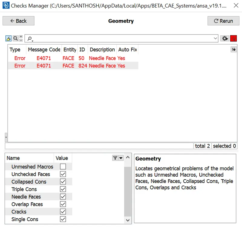
To clear these error we can go with Both manual and automatic fix,here I fixed with automatic Fix option.
GENERATE MIDSURFACE:
To generate midsurface we have to find the thickness of the model
Go to Utilities_Measure and select the two Points/Nodes.
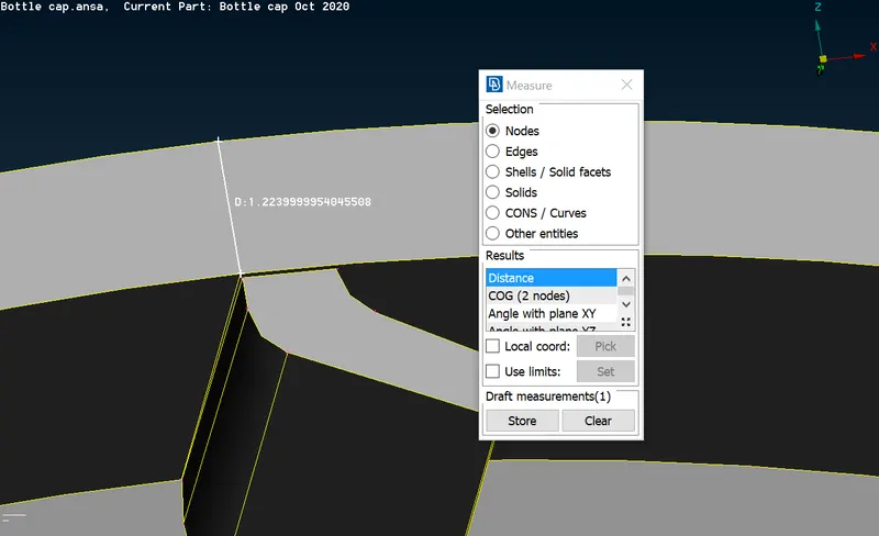
All the different thickness ha been measured and ready for the midsurface
- Midsurface are done in two different way based on the shape of the model
- Offset and middle tool in Faces are used
To get a mid between the rib first we have to remove the fillet with small distance
For that we are using Dach in Faces
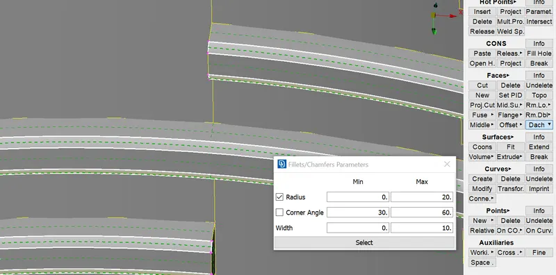
After remove Middle curve have been taken and projected that curve line to perpendicular midsurface to create a new midsurface of Rib
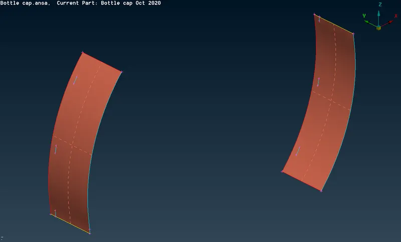
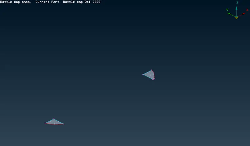
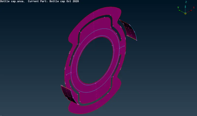
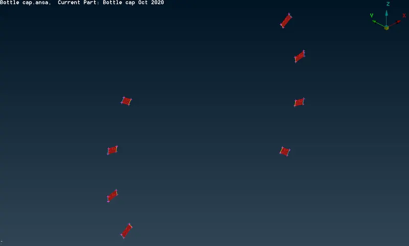
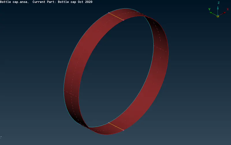
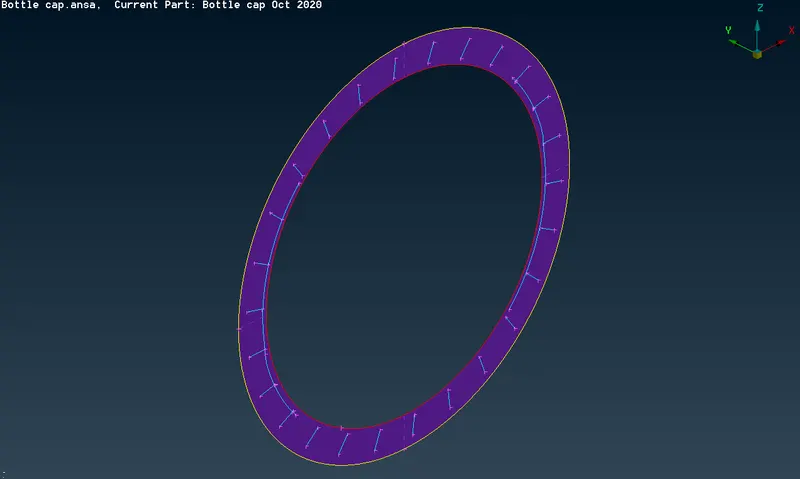
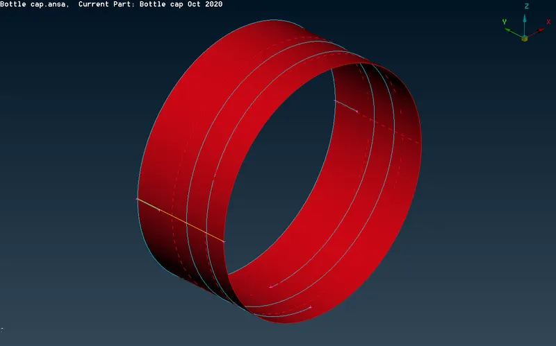
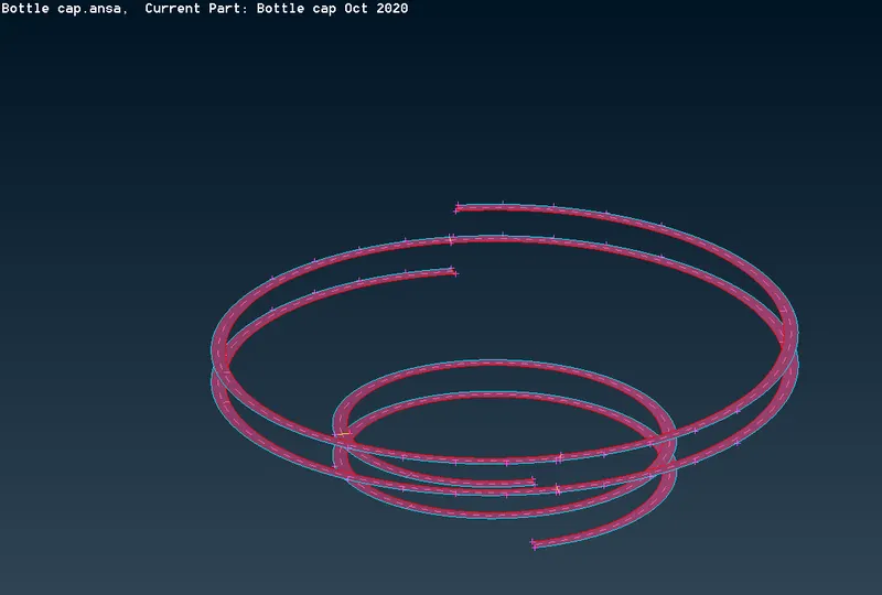
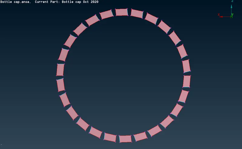
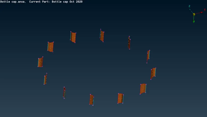
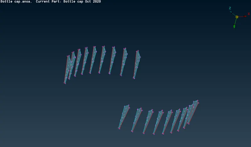
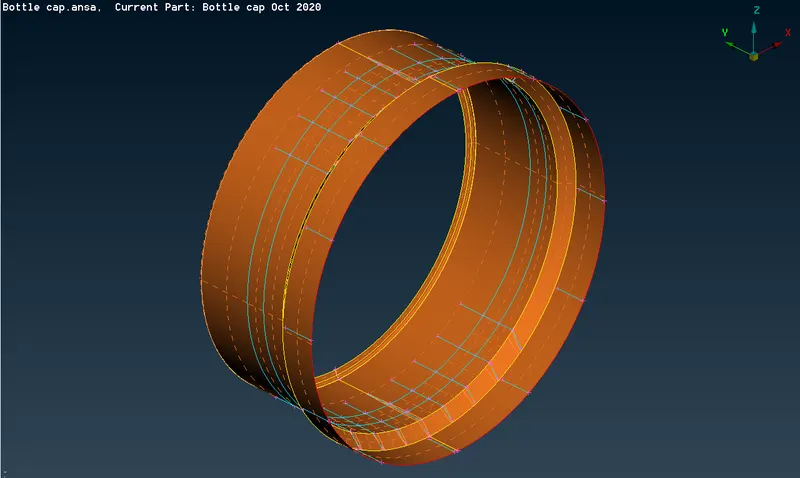
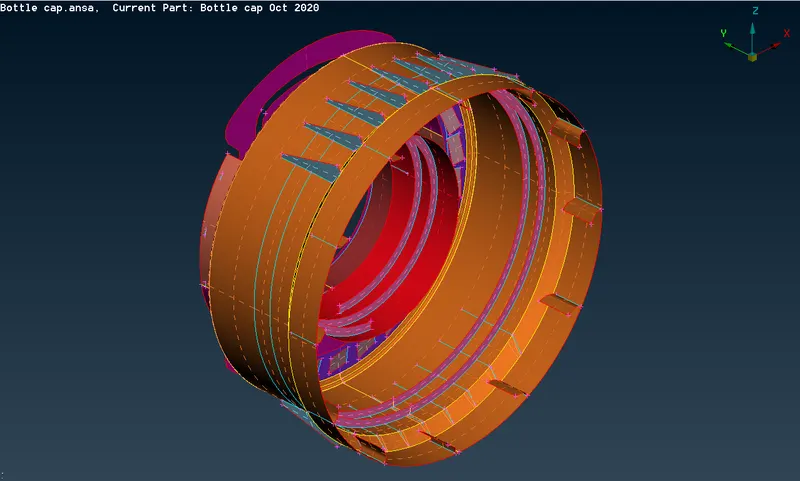
Midsurface of various thickness are shown below:
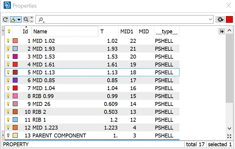
PROPERTIES FOR THE DIFFERENT THICKNESS:
MIDSURFACE WITH PROPERTY GIVEN ARE SHOWN BELOW:
- Before mesh clean the geometry by topocleanup and cut option to get a better meshing
- Input the quality creteria value by pressing F11 and enter the given numbers.
- Enter the mesh parameter as per given target element length
- Go to modules_Mesh generations_Best and start meshing each surface
MESH ELEMENT AND ITS FAILURE:
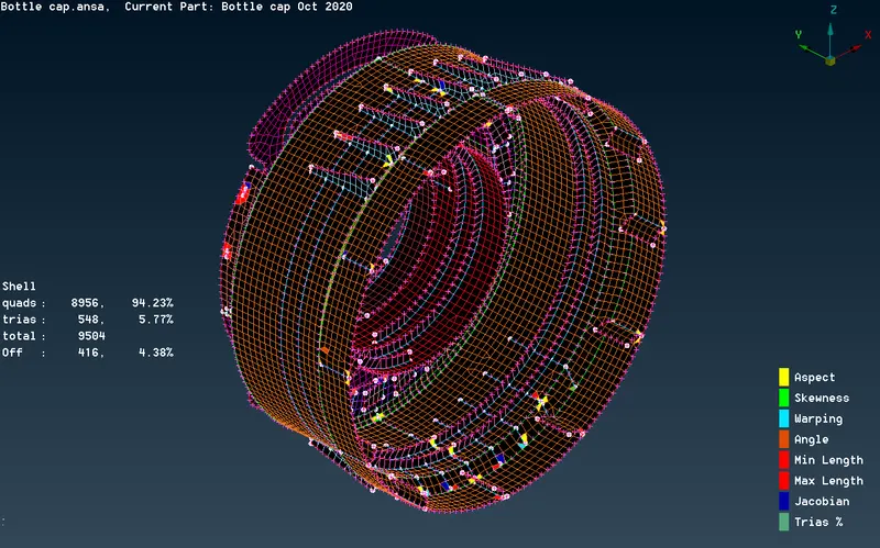
To clear the failure and to get proper mesh flow we can use the following methods:
- RECONSTRUCT on FEM.To apply this select Modules buttons_Shell mesh_Reconstruct
- SMOOTH on element.To apply this select Modules buttons_Shell mesh_smooth
- SPLIT AND SWAP on element.To apply this select Modules buttons_Elements_Split/Swap
- EDGE2PARAMETERS on macros.To apply this select Modules buttons_Macros_Edge2parameters
- Increase or decrease the node numbers.To apply this select Modules buttons_perimeters_Number/num+/-
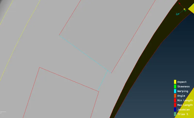
FAILURE:
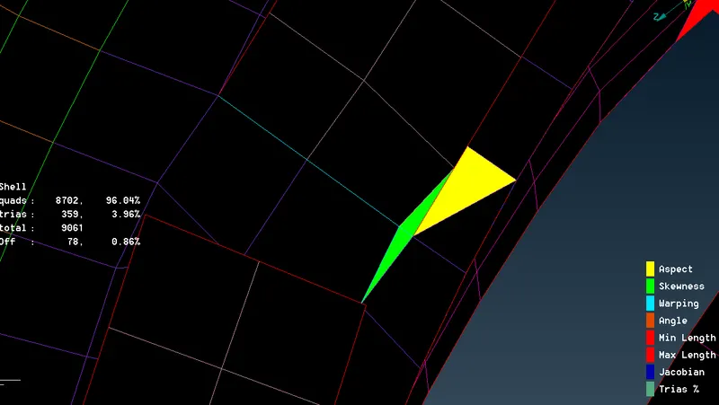
REASON:
- When there is triple cons interacting each other failure will happen
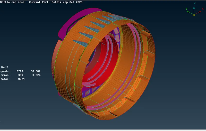
FINAL OUTPUT:
LEARNING OUTCOMES:
At the end of this challenge I can able to:
- Perform geometry cleanup for any Plastic component.
- Generate Midsurface manually without using automidsurface.
- Generate shell Mesh for any Plastic component and knowledge of quality creteria.
- Identify quality failure and clear the failure and improve the mesh quality.
CONCLUSION:
Hence the geometrical error and mesh has been performed successfully.The thickness has to be generate after meshing.Quality failure are cleared and also got a proper mesh flow with low trias.