Week - 4 - 2D meshing for Plastic components
AIM; To mesh the given Plastic Bottle Cap model, according to the given quality criteria.
OBJECTIVE;
Import the cad model in to the ansa Gui.
Perform the toplogy cleanup on the given cap model.
Generate the mesh on the given component.
Pass the all given quality criteria.
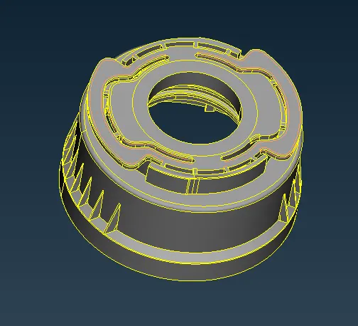
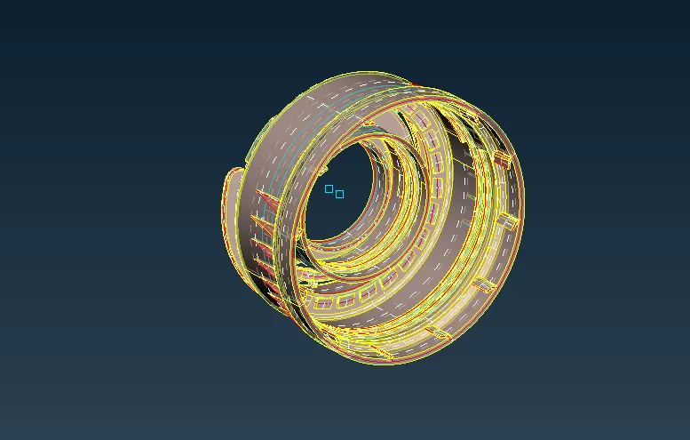
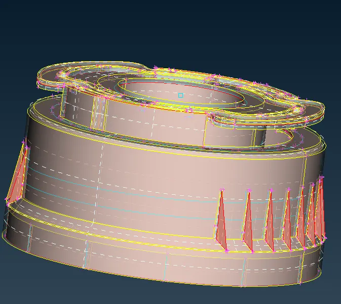
GIVEN MODEL;
PROCEDURE
- We need to import the model.
- geometry checks have done for the model properly and fixing those issues.
- Measuring Thickness.
- EXtracting the midsurface.
- Removing the unwanted construction lines, before meshing.
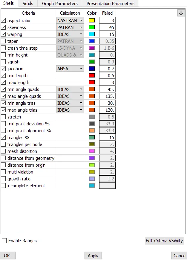
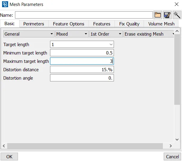
- Setup the mesh parameters and set up the quality criteria.
- Generate the mesh on the model.
- Assign the thickness to the components.
1.We need to import the model.
For importing the model into the Ansa Gui, File>open> enter ok.
2. Geometry checks have done for the model properly and fixing those issues.
Tools> checks >geometry >all entities >execute.
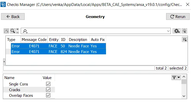
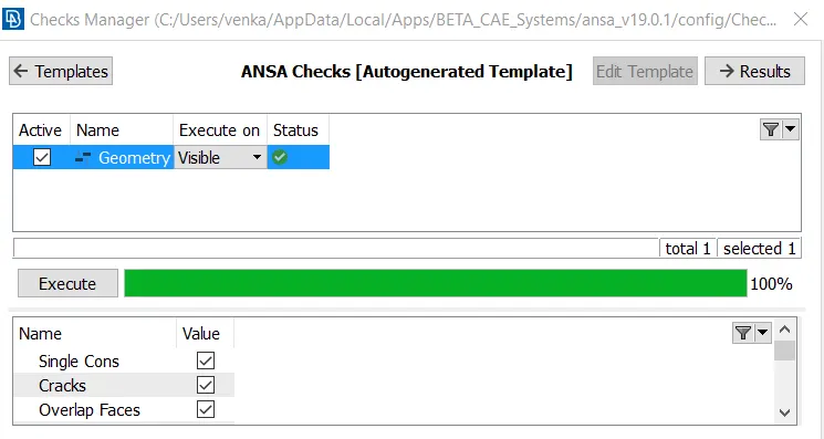
Perform the topology clean up which ever left remaining after fixing the geometry.
3.Measuring Thickness;
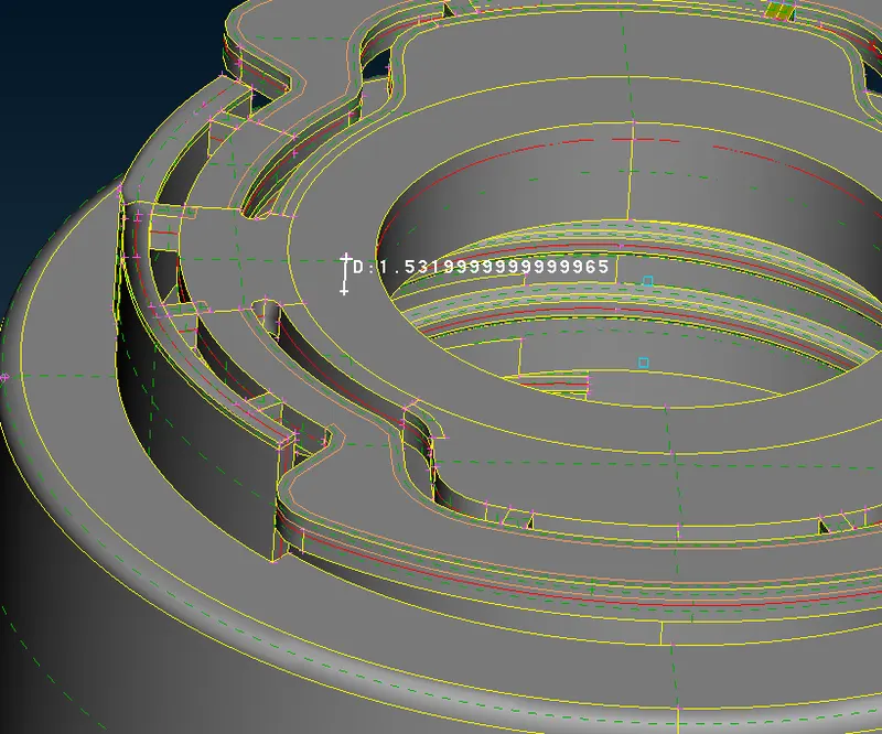
We have to measure the thickness and find the model whether it is plastic or sheet metal component.
- Normal way to check the Measuring thickness among the geometry.
Using the nodes and cons/curves.
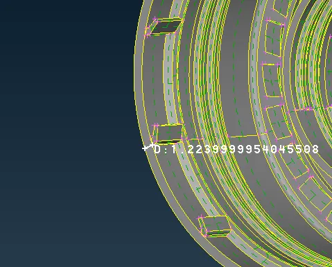
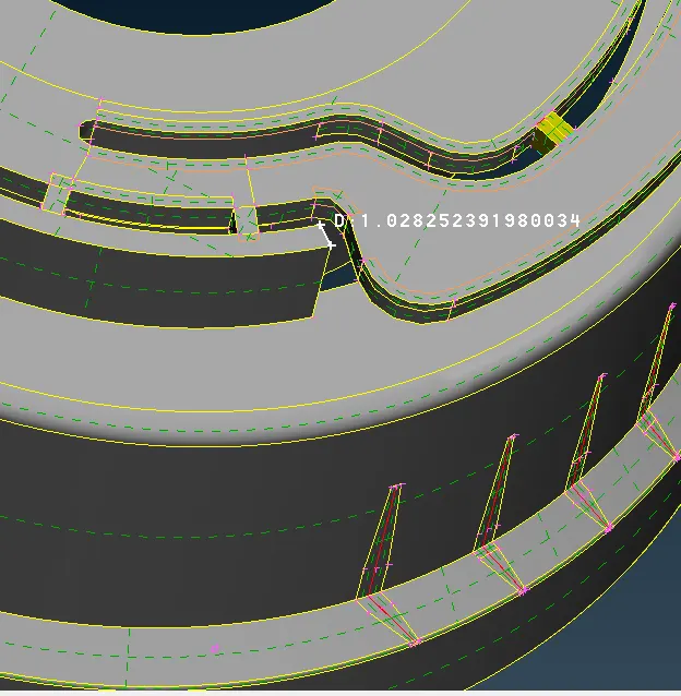
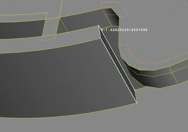
- By creating a split in the geomotry , next hide and project the split for the geometry and insert the points to the mid of the projected splits finally measure the thickness of geometry part.
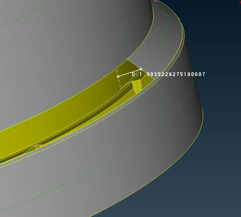
- By creating weld spots on them and project it to anther side and measure the thickness of the geometry.
4.EXTRACTING MIDSURFACE;
Since it is an plastic model it has varing thickness with different complex parts, we extract the mid surface in many ways midsurface some of them are by using middle and middle(multi), offset in faces and middle curve for complex region shapes.
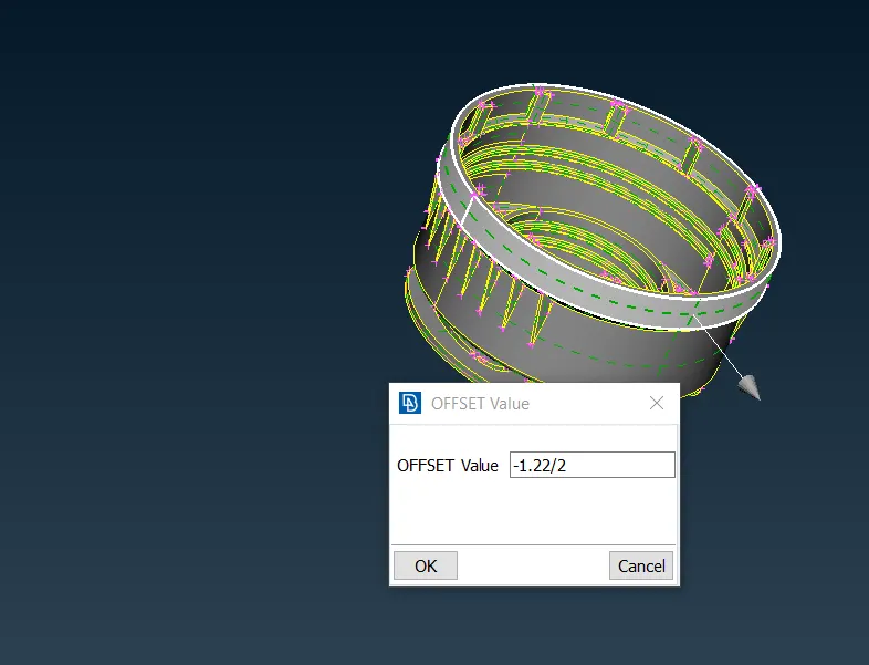
OFFSET
- Measure the thicknesS> then select offset in one side of the faces > give the value of the thickness and click middle mouse.
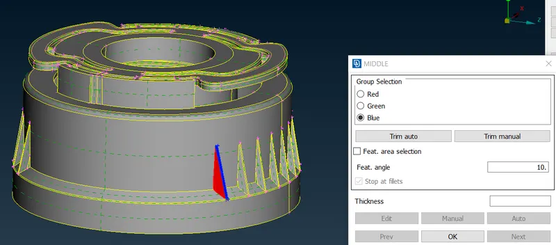
MIDDLE(multi)
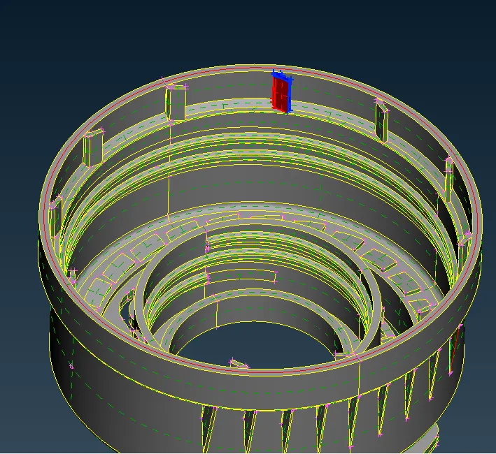
- If there are multiple faces and unable to take mid surf by normally we choose the middle(multi) option. we will select the faces by different color orientation and finally it will give us an apporiate midsurf to the ribs.
MIDDLE
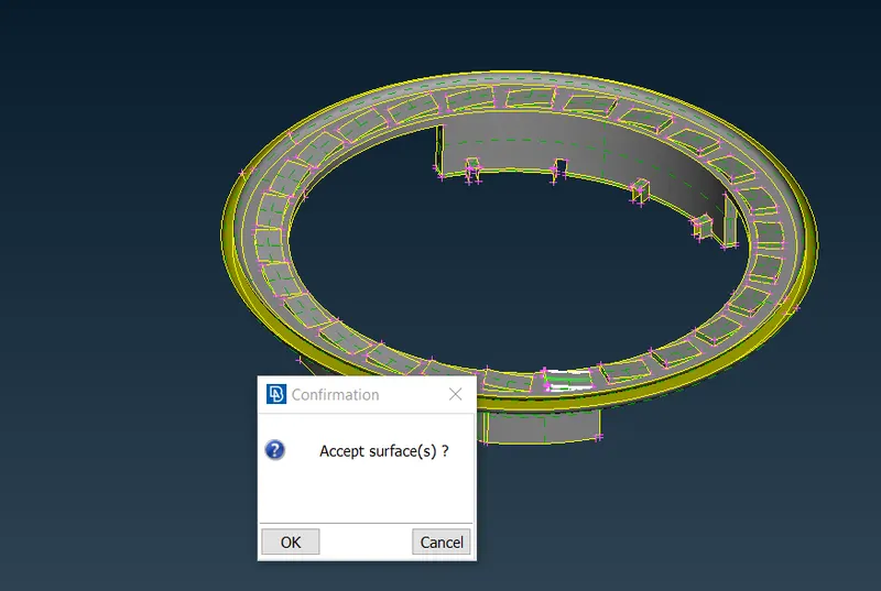
- This middle will helpful for taking an mid surf of the side by side model components and staisfies model component.
- Here we use the not option inorder to hide the seleted entity and make the easier to view to other components.
Curve(Middle)
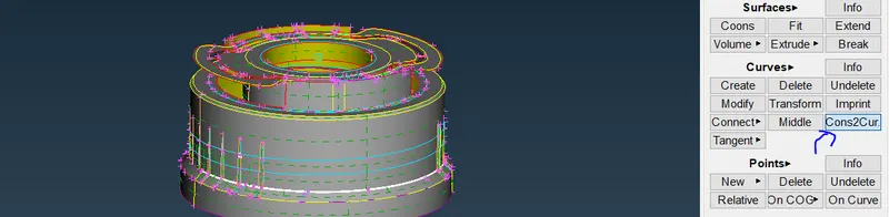
- curves > middle >select the cons and click middle mouse button and it will creates curves in between the cons .
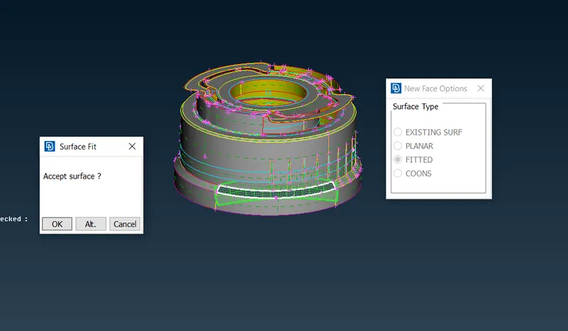
- This method used for complex parts with variable thickness and extract the middle curve which was shown in the figure. we need to create a new surface in between the curve and projected line surface.
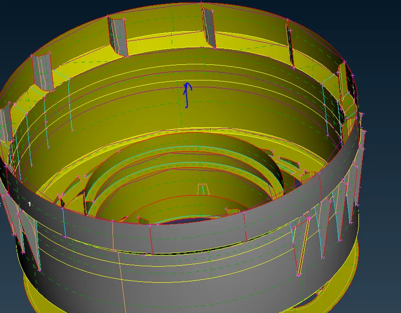
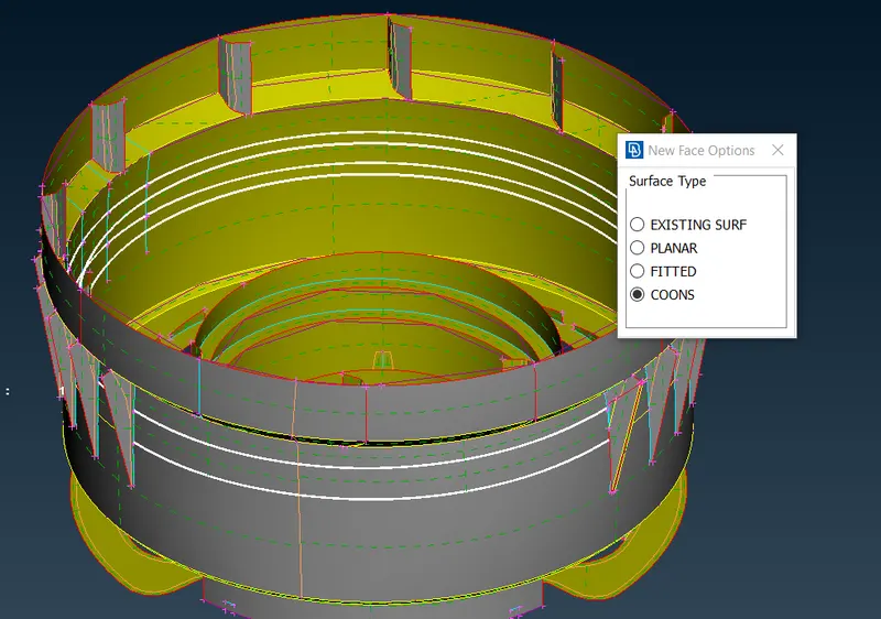
faces> new > cons , select curves and projected lines there it will form a surface.
Transform > copy > rotate > set COG points and angle.
- This command help to create all the surfaces for taking an mid for one surface by using rotate option, it will take mid for other surfaces which lie in the circle format.
- First go to the transform, select the entity and go to the rotate option where we can select the no of steps to be produced, next set the coordinates with the cog points and finally gives the angle for the entire surface and finish the operation.
- Extend the ribs and remaining parts to the surfaces properly, after taking the midsurfaces to the components.
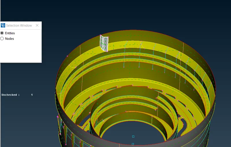
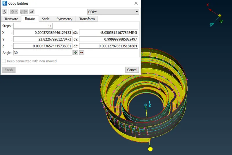
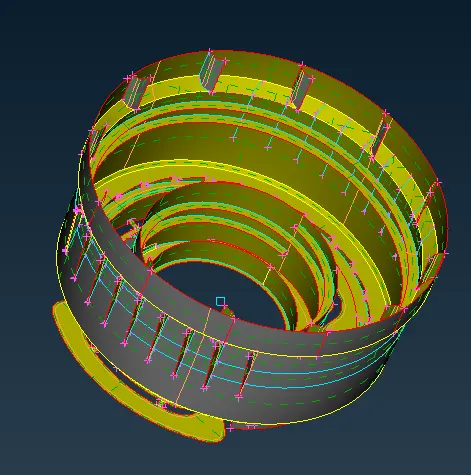
Simillarly transform and rotate all the ribs which have done for the above section.
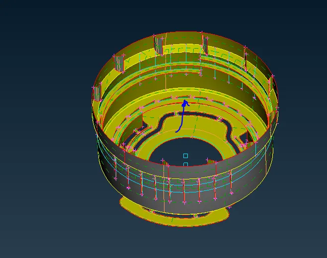
5.Removing the unwanted construction lines, before meshing.
- Since the geometry as an lot of unawanted lines, we form the imaginary curve among the surfaces and after we create an new surface by referring those formed curves.
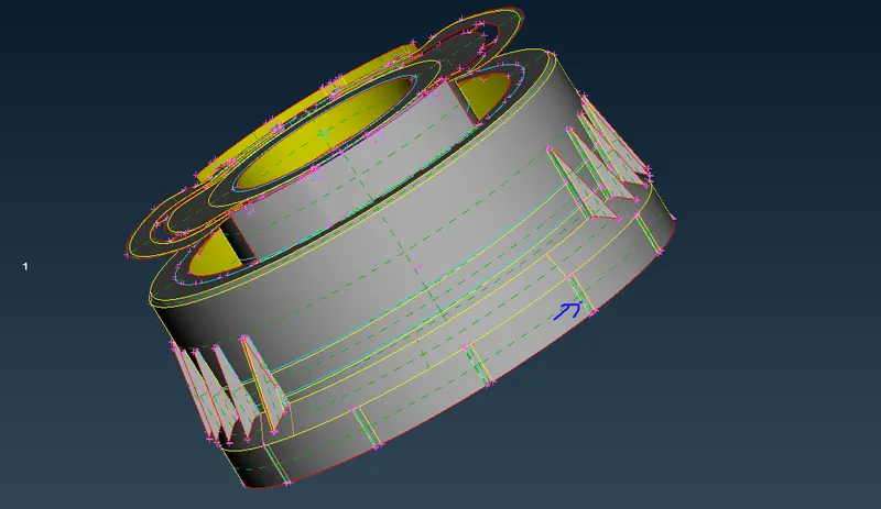
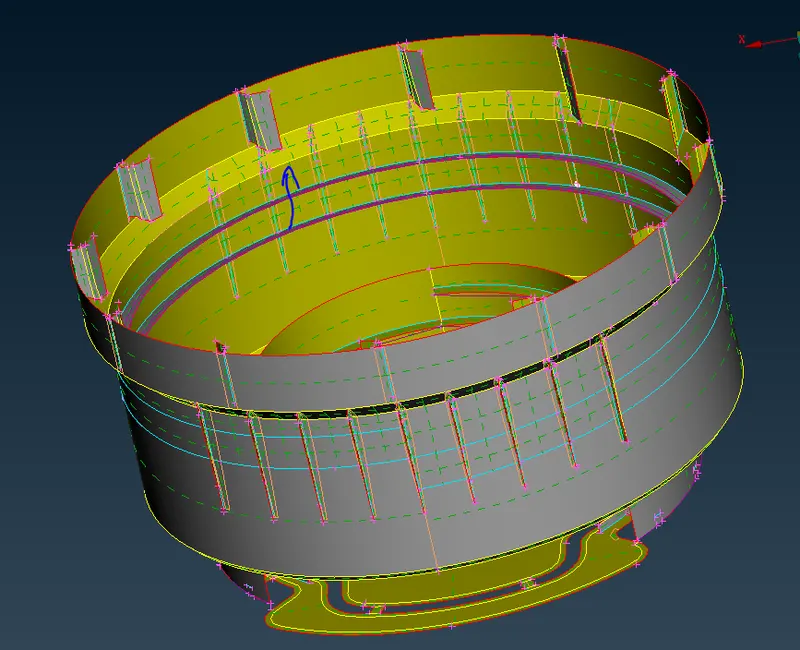
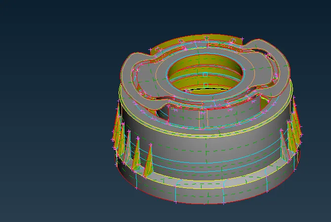
ENTIRE MID SURFACE;
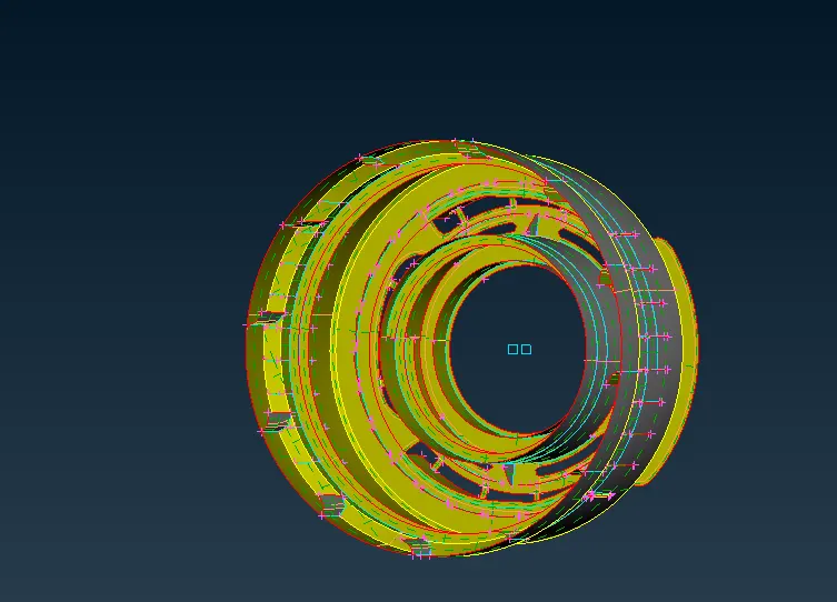
Transprency mode
- Go to the property's, where we select the original surface and on the transprancy.
- enable the created midsurf indication should on.
- change the Draw mode entity to the PID mode, where we can transprancy clearly.
- Transprancy gives the good visualization of understand the original and midsurface taken from the geometry.
6.Set the quality criteria and mesh the model.
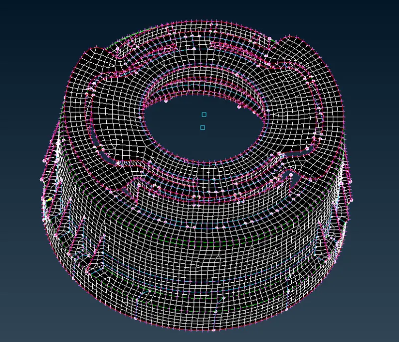
7.Generating the Mesh on the Mid surface.
- For generating a meshing, we change the topo mode to the mesh deck
- Next, we need to give perimeter and macro length > select the surface and give the target mesh value to the model.
- we can start meshing, by using the Best option and select the surface, generate mesh on them.
- inorder to obtain the better mesh we should the reconstruct option.
- For quality fixing we different options such as egde2perimeter, grids, paste, split, swap, join and also smooth the mesh for obtaining the better results.
8.Assign the thickness to the components.
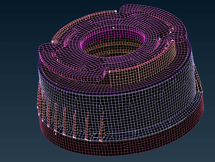
For assigning thickness we have to create the set pid's to the components and assign the thickness value to the component.
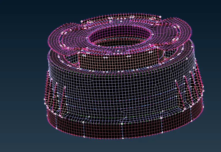
Go to the quality paramters> click draw shell as solid and apply.
CONCLUSION;
- Learn about to the taking midsurf surface to the plastic component.
- Perform the toplogy cleanup and fixing those parametrs on the given cap model.
- Usage of transform option(rotation), where to save time.
- Removing the unwanted construction lines, before mesh generation.
- setup the quality and clearing those errors.
- Compramising the quality in some places.
- Assigning the thickness.
LINK;
https://drive.google.com/file/d/1Eap9IfnqTVFqG5f2dFoG444bD-vOVI6O/view?usp=sharing