Week - 4 - 2D meshing for Plastic components
BOTTLE CAP CHALLENGE
AIM:
- In this challenge the given model is Plastic Bottle Cap, we are going to create the 'FE model' for this component using the 'ANSA preprocessing tool'.
CHALLENGE EXPECTATION:
- Check for the geometrical errors and take the mid surface CAD model, and Mid surface has to be extracted.
- The extracted Mid surface has to be meshed with the proper Quality mesh flow under given quality criteria.
- PID and Thickness assignment has to be done for all the mid surfaces.
PROPERTIES OF THE COMPONENTS:
- Materials which is having less than or equal to 6mm can be meshed with 2D Meshing.
- In 2D Meshing, we can classify the materials into two types.
- Sheet Metal Component
- Plastic Component
- The material which is having Linear Thickness throughout the Body is known as 'Sheet metal'
- The material which is having Non Linear Thickness is 'Plastic Material'.
PROCEDURE:
- CAD SET UP
- CAD Geometry
- Model Clean Up
- CAD MODELING
- Meshing
- FINAL CHECK
- Maintaining proper Mesh
- Assigning Thickness to Mid.surface
PREPERATION OF MODEL FOR MESHING: (Part -1)
- I used to check the existing PID’s in the ‘Property Card', in this Bottle cap model there is only one PID was there.
Steps to be followed in Begining:
- Import the downloaded geometry using File manager and then we have to set 'Cons Resolution' for the parent geometry, It is present in (Mesh module/Perimeters Group/Length)
- Next step is Orient (Topo module/Faces group/Orient)
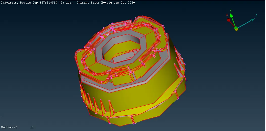
- This is our Bottle Cap model.
TOPOLOGY CLEAN UP: (Part - 2)
- Now it is time to Geometry Cleanup.
- Before start meshing Geometry Check is necessary, because in Original CAD geometry there might be some errors in cons.
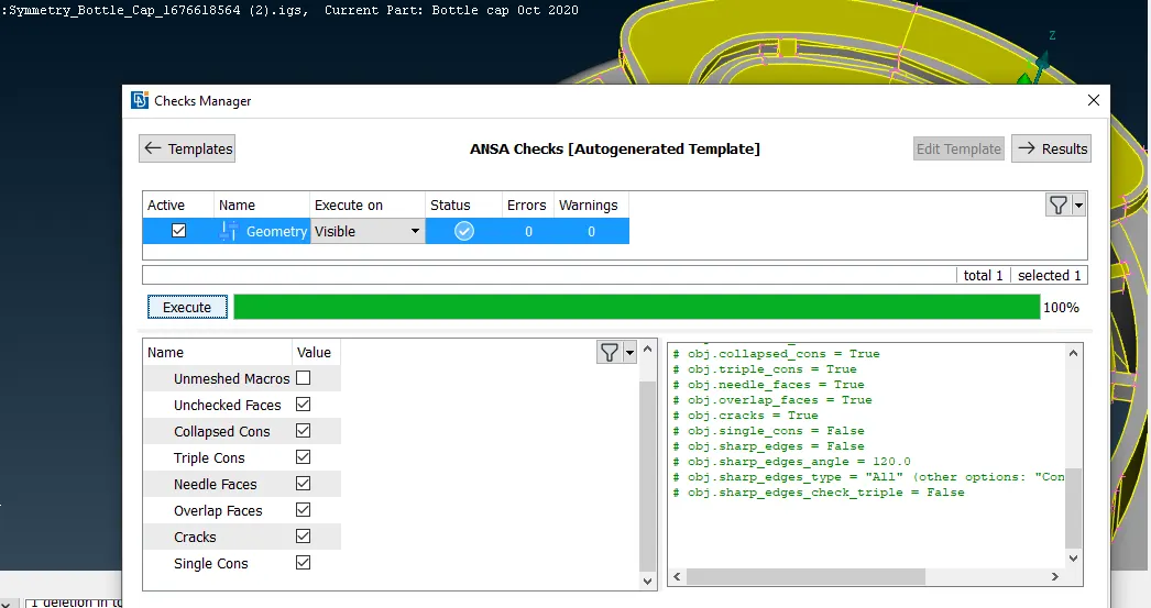
- In our 'Bottle Cap Model' only two errors were present when perform the geomentry check.
- We can find the option (Tools/Checks/Geometry) here.
- In ANSA there is an option called 'AUTO FIX', i used this function to fix my errors, because it saves more time.
THICKNESS CHECK
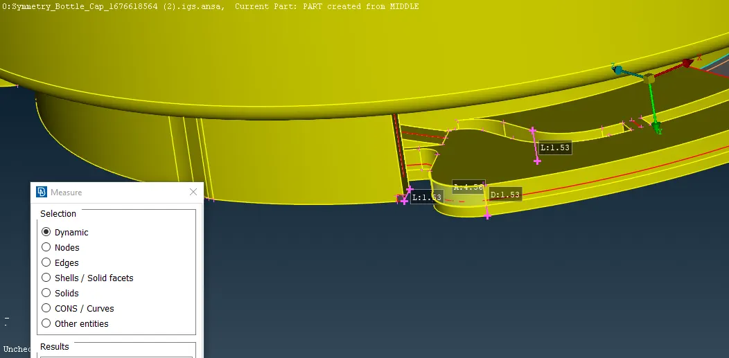
- We can see it clearly this BOTTLE CAP model has Non uniform thickness so we can consider this is Plastic Component.
MID SURFACE CREATION: (Part - 3)
- We have prepared geometry. Next step is creating the mid-planes
There are Two methods to create Mid plane
- Manual Method
- Automatic Method
- In this model i used the Manual mid.surface to create the Mid Surface, using the Option (Topo Module/Faces Group/Mid.surface/Casting)
- The Reason I go with the Auto method because this model has different thickness in various areas, so the mid surface extraction save my time a Bit in auto method
- On the 'Single middle mouse button' confirmation the mid surface creation is done easily.
BEFORE CREATING MIDSURFACE
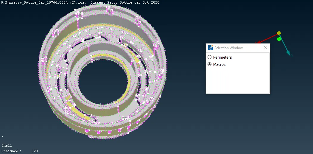
ASSIGNMENT OF LENGH
assign lenth primeters to capture proper resolution at the time of meshing.
perimeter and Macros lenth should be the 1 mm.
STEPS TO FOLLOW BEFORE MESHING:
- We have set the Quality criteria and mesh Parameters properly as per the given requirement, because when we use the 'CASTING' option, the mesh also be Generated automatically.
in the casting method ibserved that the mesh generation and mesh flow was not proper,
so we use manual method to create mid surface of the component.
CREATING MIDSURFACE
To creating mid surface before that that do the cut section beacuse the component
is symetric. after that do the mid surface and meshing scenario.
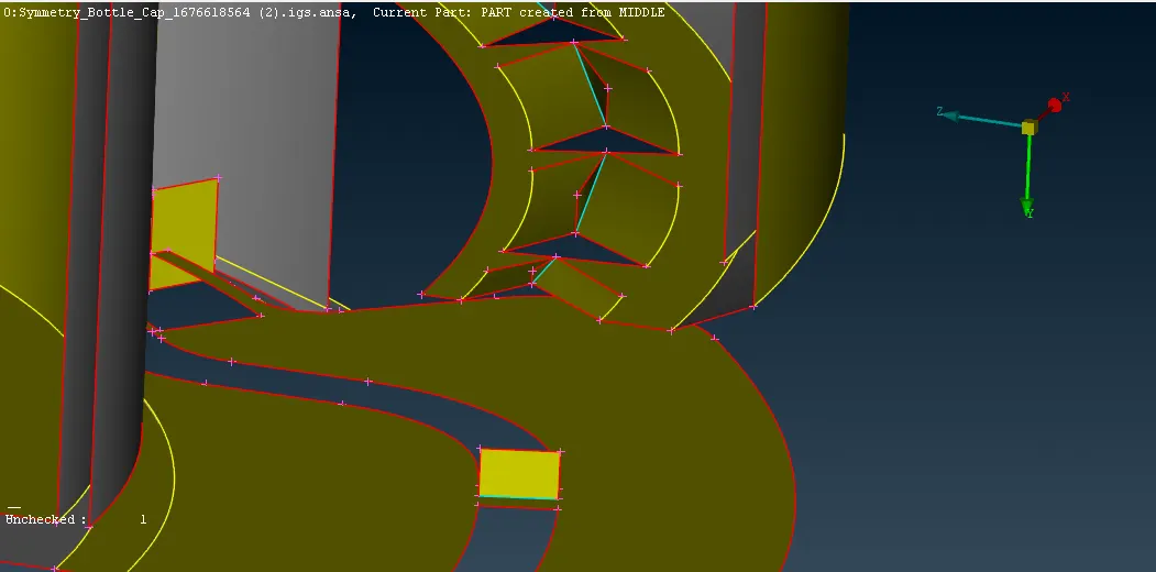
EXTRACTED MID SURFACE PID
- As we can clearly see this mid.surface that created by the 'CASTING' is not that much good.
- so we try to create midsurface by using maunal method using tool offset tool and middle tool.
- Some areas are not properly aligned compare to the 'PARENT GEOMETRY'
- So it is our responsibility to clean it up and make it proper.
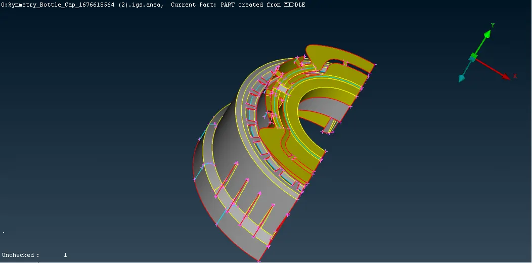
after midsurafce we some fillets are not attached to parrent surface, we have to use project or use extend tools.
- To Capture this feature I use the 'Middle curve' option to create it as a Reference of Parent Geometry. (Topo module/Curves Group/Middle)
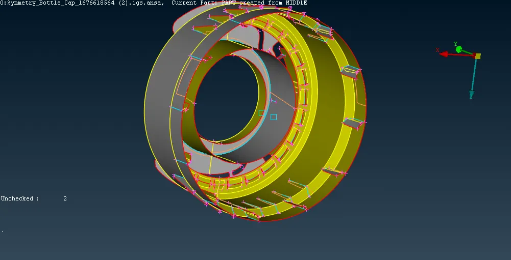
after the the succesfuly doing the midsurface the now we have to do the meshing by using
batch meshing scenario.
BATCH MESHING.
Before going to do the meshig we have to check mesh parameter, assign quality criteria and create model browser
assign PID to midsurface.
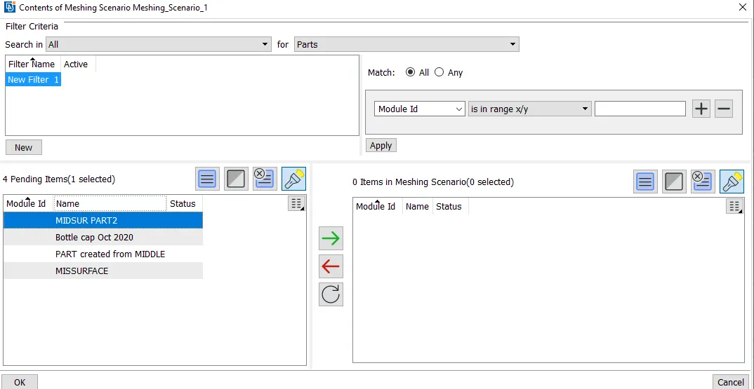
- with the help of Batch meshing manager create new contents assign model.
- after that select component in the meshing scenario and click on run.as shown in the below image.
- meshing scenario succesfully completed and its take time to execute 42 sec.
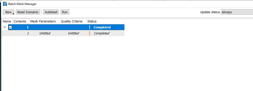
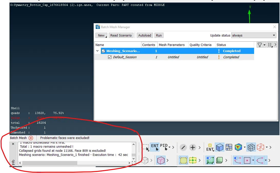
- after sucessfuly meshing with the help of batch meshing tool.
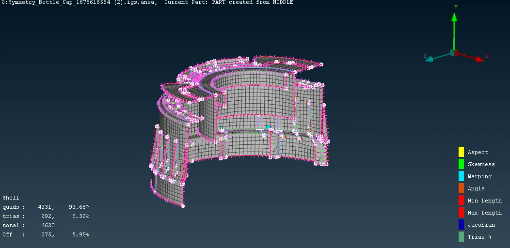
- there are some element failure for quality criteria, So it is our responsibility to clean it up and make it proper.
- to cleare failure element we use tool move, smooth, split, swap and map, reconstruction.
SYMMETRY MIRRER
In order to use transfer option doing the duplicating mesh symetry.
select X1 X2 and X3 point as shown in the below image to symetry mesh surface.
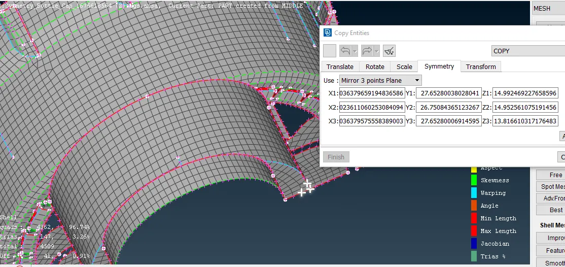
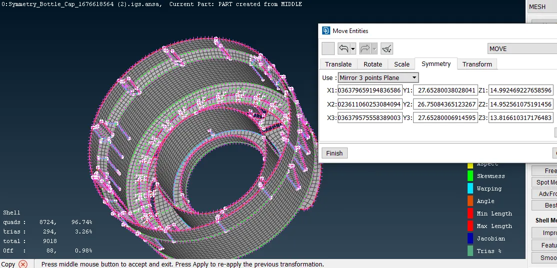
After symmetry mirrer was done but fillet wasn't attached in proper diection and some fillets are found to be missing.
so we have to take traslate tool and use option rotate and then create all missing fillet.
for that first we have to centre point using the tool ...
In order to use the rotate option for duplicating this mid surface of a tooth, axis rotation is required. in order to create of a that,
we should have at least 2 centre point.
- to create centre point, ON COG option is use in point.
- select two circlular line one by one to create point one by one.
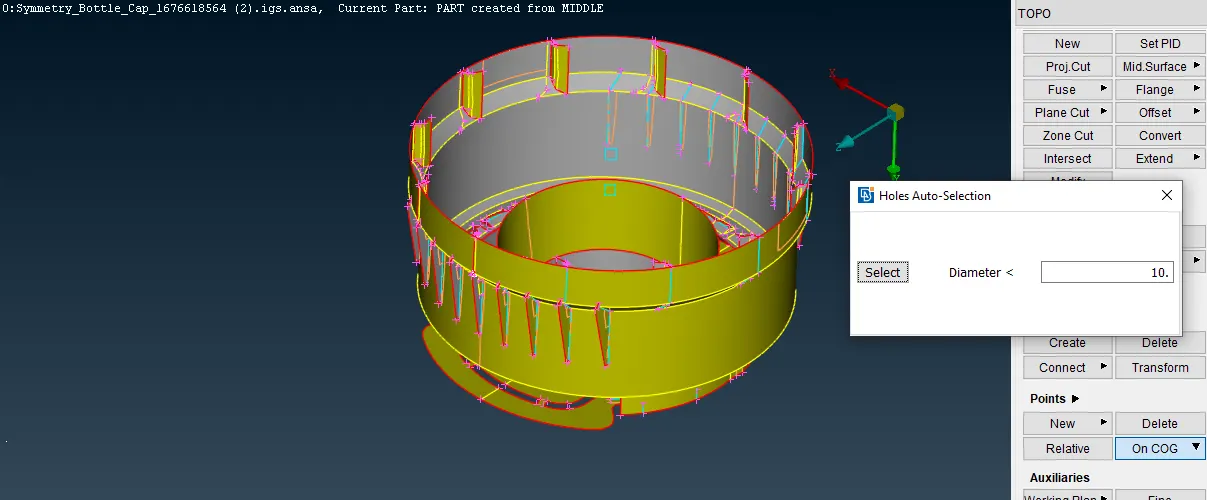
in order to create axis of rotation option rotation, two COG point at the centre with different height should be required
- in order to do so, Go to ON COG and select any two circle line whith are at differen height.
- now click on the trasform icon and then click on the copy select entity as the meshing and midsurface of fillet.
- fill the deatils as shown. total no of fillets are 13, one fillet mid surface are already was done,
- so in step we need to write 12 fillets more mid surface.
-
select two point to define the rotation vector, press middle mouse button to apply.
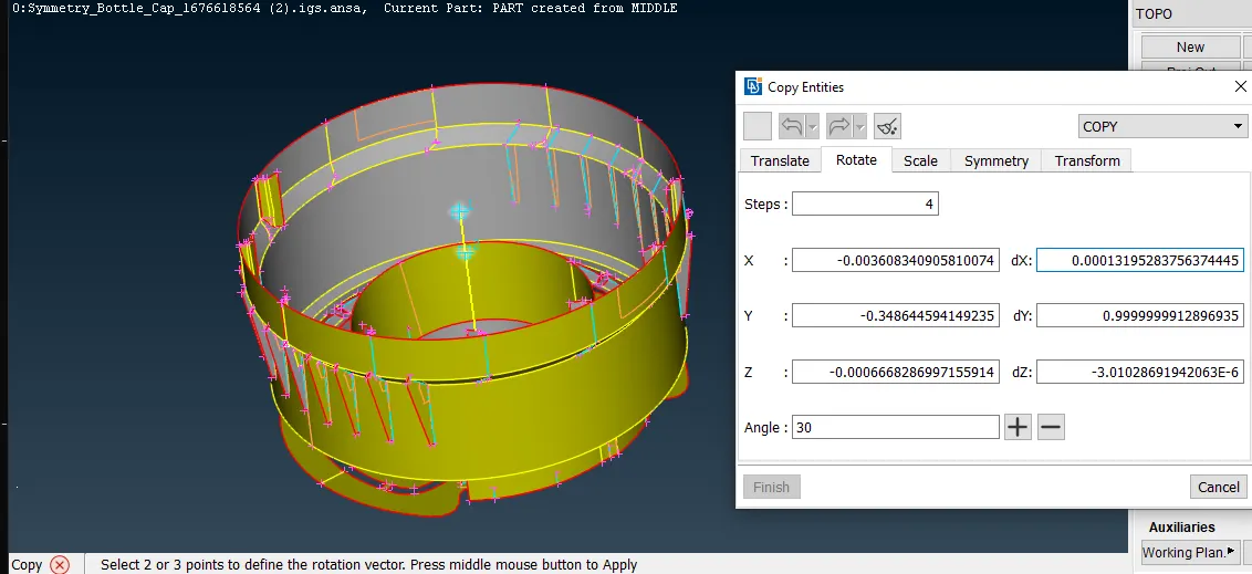
- click on X box and then select COG point. similarly click on the dX box and then select COG point 2. axis of rotation will be created.
- angle between to two entity =total angle of circle/ total no. of fillets.
- after doing this we can observed that 12 new mid surface can be created.
- FINAL CHECKING OF MESH:
- Once we done with the clean up and corrections of the midsurface, need to work on the OFF ELEMENTS and the MESH FLOW.
- Some areas are not meet the 'Quality Criteria', where the areas Triple Cons closely present in the model, Elements has failed .
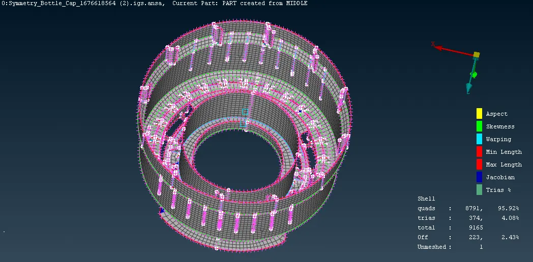
- In the Above picture, the critical areas are mostly off elements were present.
- This was the challenging task for me, I managed to get the better result as much as I can.
HERE IS THE BEFORE & AFTER RESULT OF OFF ELEMENTS:
- This is the data in the above picture that i receive after I corrected the Distorted casting Result.
- In this window the Off elements percentage was high.
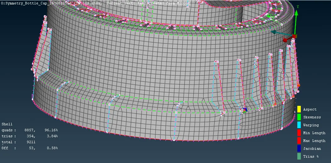
- After dealing with Off elements and mesh flow, this is the Final outcome of the Bottle Cap.
ASSIGNING THICKNESS TO THE MID SURFACE:
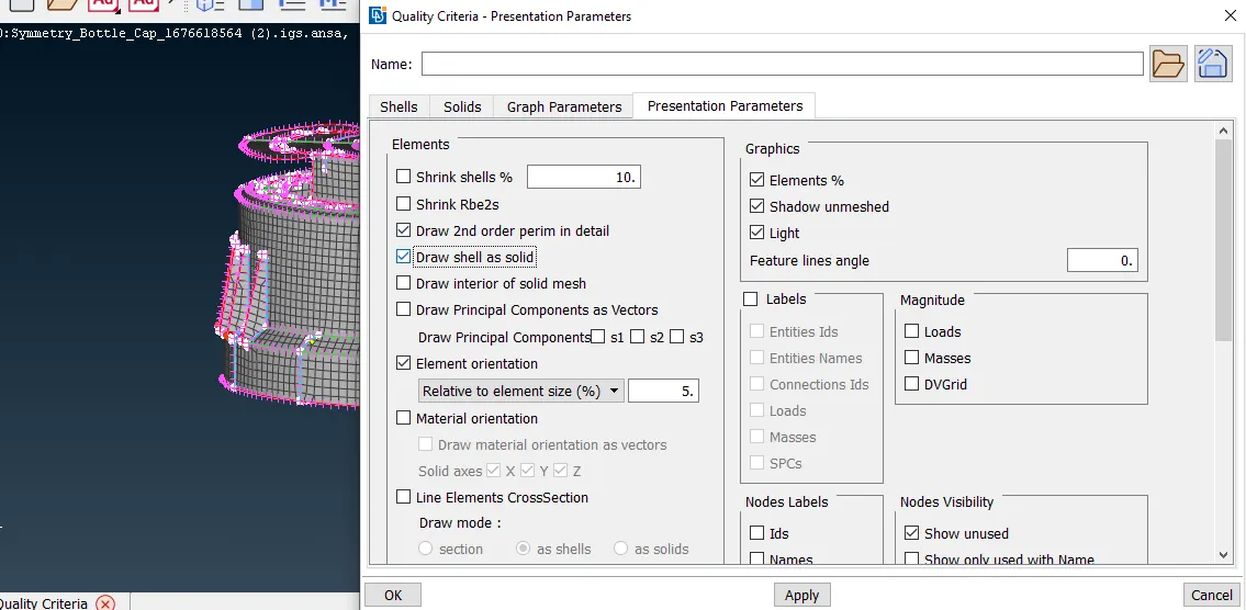
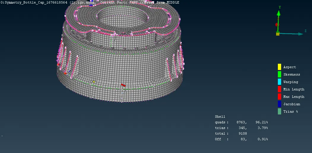
- Thickness has been assigned to model by using quality criteria presentation paarameter with check by drow as a solid shell.
RESULT OUTCOMES:
- Finally achived Trias with 3.84% and OFF Elements with 0.58%
- Good Mesh flow, no trias touching on the Circle and no trias touching the Free end.
- No Rottating Quads keep maintained, No Opposite Trias are present in the FE model.
- No any other Feature Lines missed while meshing.
- Missed Ribs, Thread and Teeth has been captured properly as per the Parent Geometry Reference.
CONCLUSTION AND LEARNING OUTPUTS:
- On the conclustion of this Bottle cap model, it was a Quiet a challenging one, when completing this model,
- I learned new commands and how they are helpful to achieve good meshing.
- The new method of Mid surface/Casting option learned in this challenge.
- It gives the confidence to meet any complicated Models can be easily face it.