Week - 4 - 2D meshing for Plastic components
Objective :
- Checking for the Geometrical Errors .
- Extracting the midsurface with suitable Midsurfacing Techniques .
- Meshing of the same component with Target element Length of 1 unit and with proper mesh flow .
- Checking for the Quality critria provided .
- Assigning the PID and the Thickness to the Mesh .
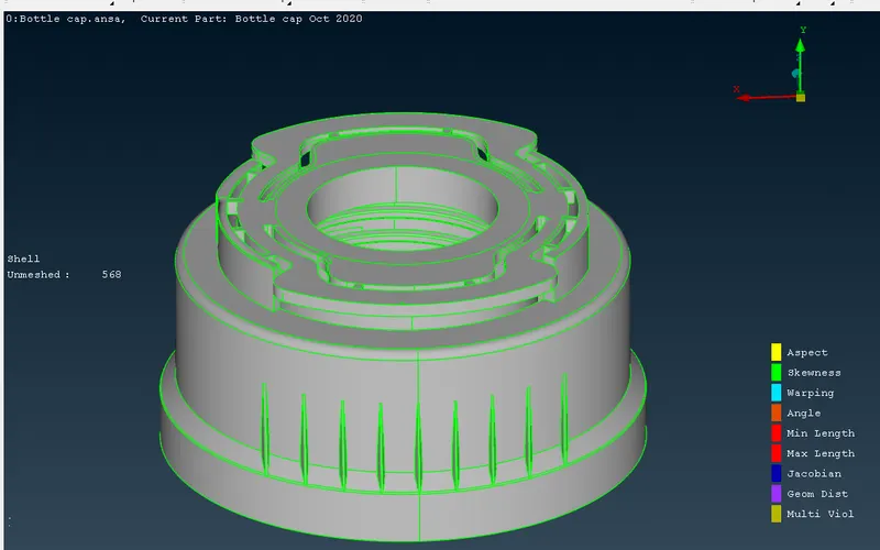
CAD Model :
Procedure :
- Model is imported and checked for the geometrical Errors .
- No any Geometrical Errors are found in this model .
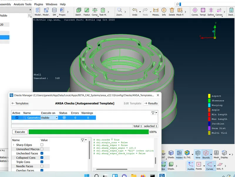
- For this Model , Midsurface is extracted Manually as this is the Plastice ciomponent , and has varying thickness.
- We will not get Proper midsurface from it .
- For Top side rib midsurface extraction , initially curves are created as this surface have varying surface can be seen below as ,
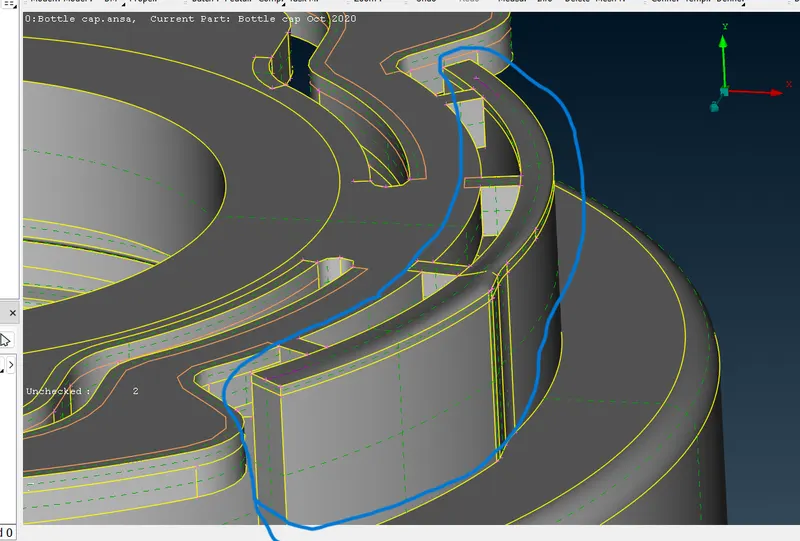
- For this Curves are created at middle of the upper face and the middle of lower cons .
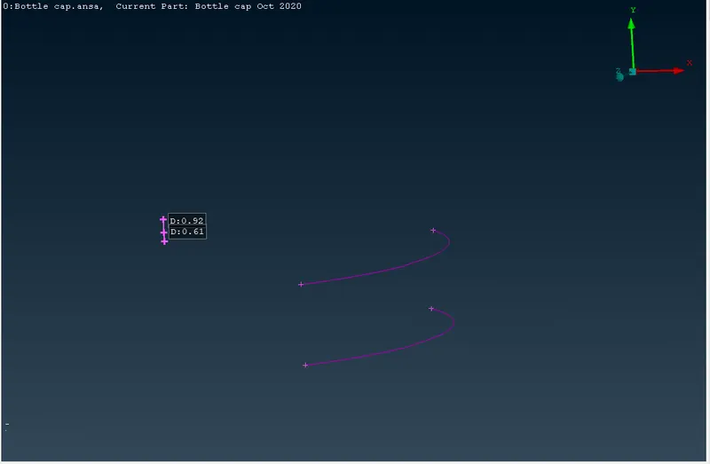
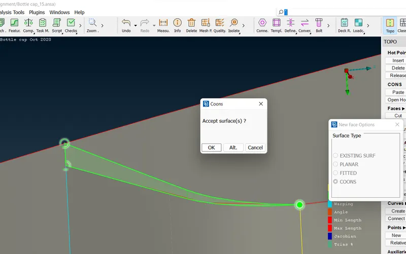
- Then Using the New surface with Cons Option , the new surface is created as ,
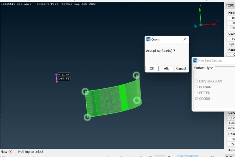
- Midsurface extracted of the same rib can be seen below ,
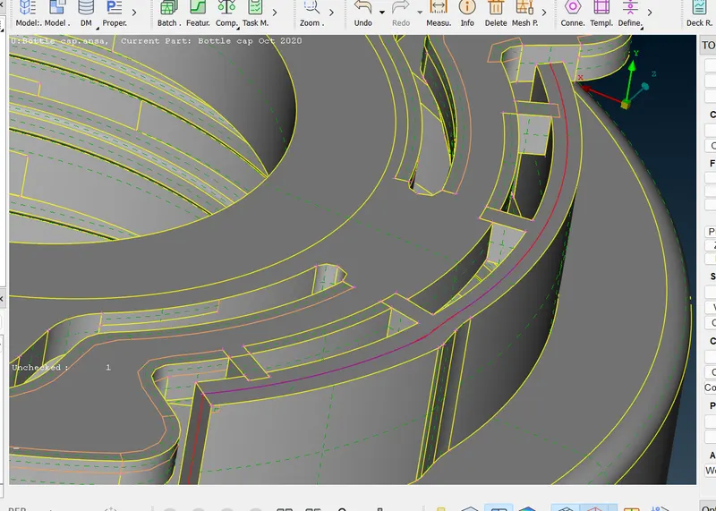
- In the same way midsurface for some other surfaces is extracted .
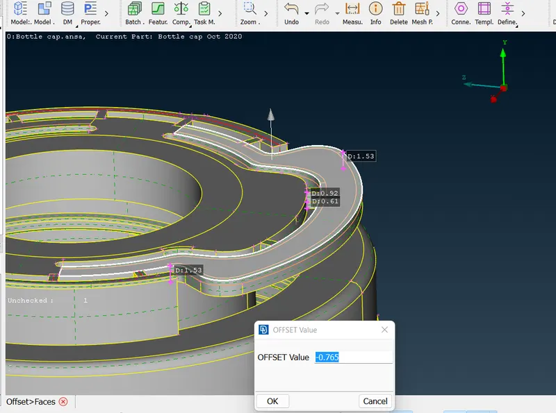
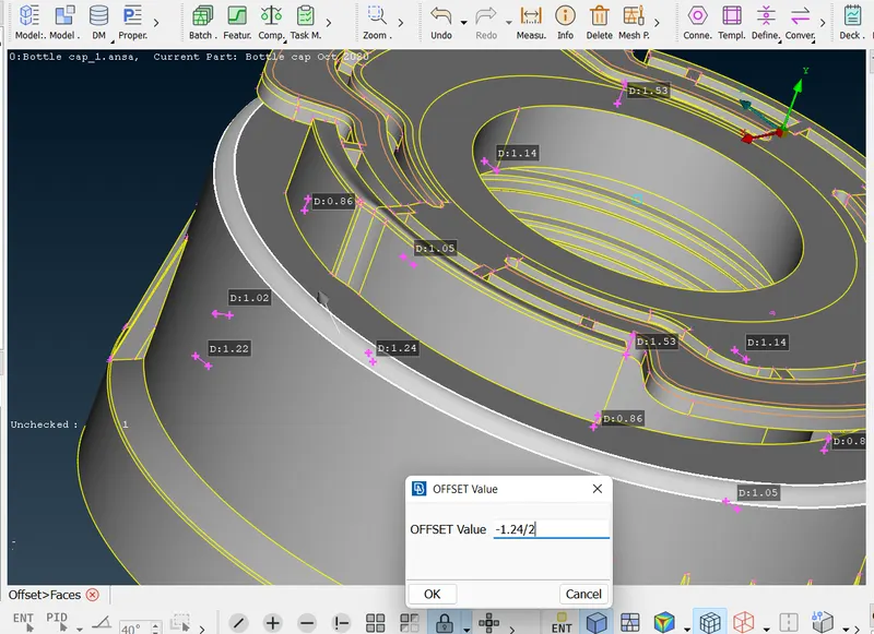
- But for the Same thickness surfaces , The midsurface is extracted using the Offset Tool , which offsets the selected face of the surface and offsets it at the user defined distance.
- The Upper surface of the bottle cap model is offseted by the 1.53/2 distance ( 0.765 unit ) as the thickness of the this surfaces has 1.53 units .
- The negative sign indicates the Surface is offseted in the opposite direction of the arrow shown .
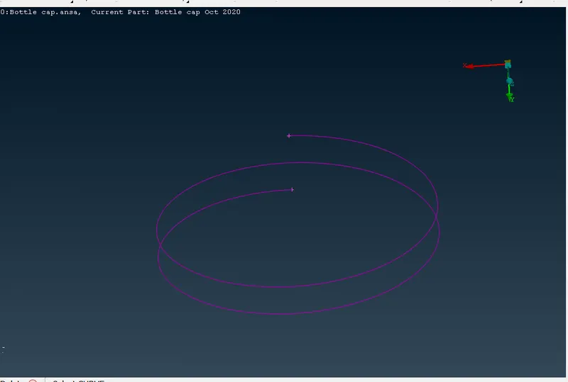
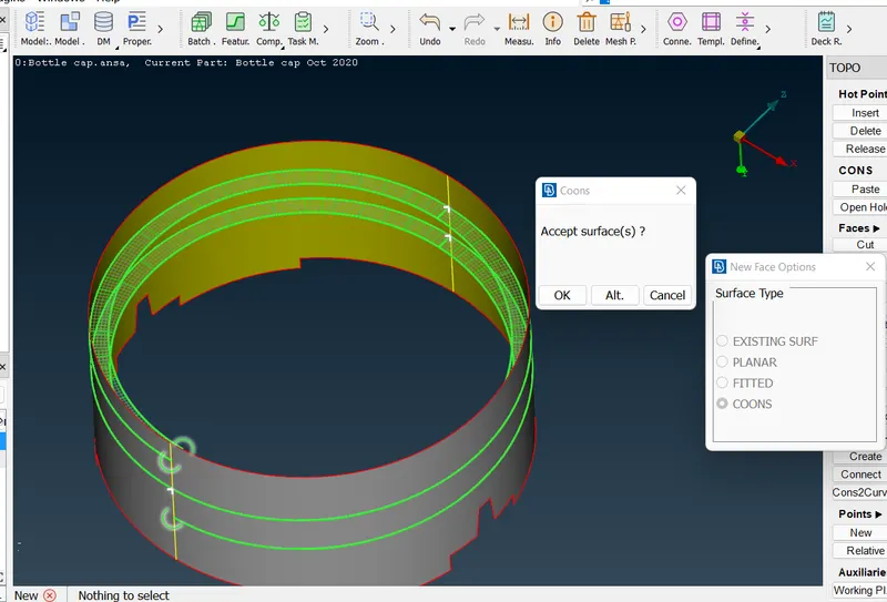
- For extraction of the midsurface of the threads of the model , Initially the curve is created at middle of the top face surface .
- WHich will create spiral like Cons as ,
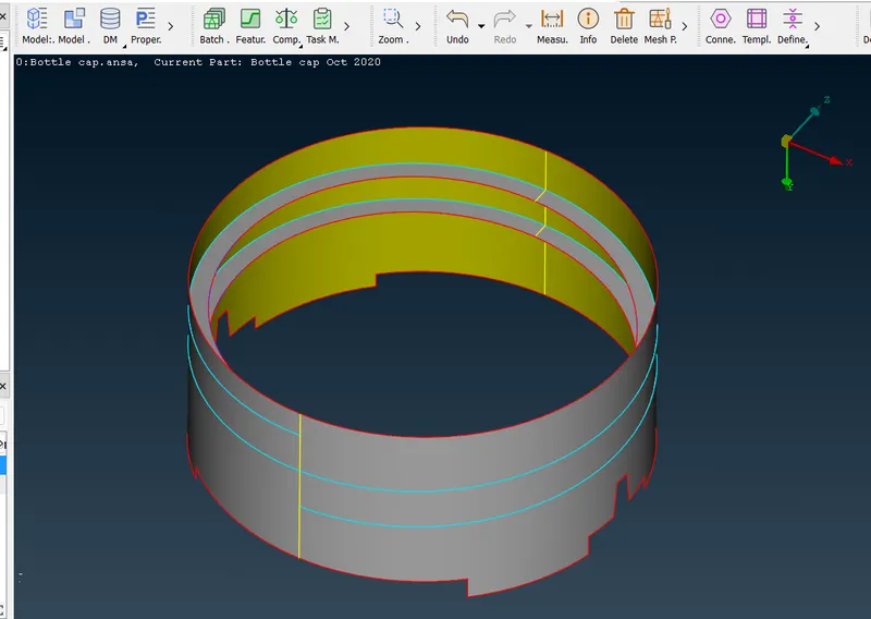
- Now isolating midsurface extracted previously the support surface of the Threads.
- And This curves is then projected on the support midsurface .
- And using the New surface tool , with cons option New midsurface for the threads is created as ,
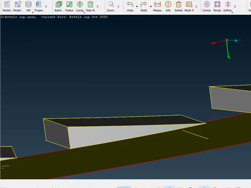
- For midsurface of the Tooths are created in the same way , initially the Middle curve is created on the front face .
- The rear edge of the surface is then projected on the lower midsurface as ,
- Using this , Cirve and the projected edge as Cons , new surface is created which is midsurface of the Tooths .
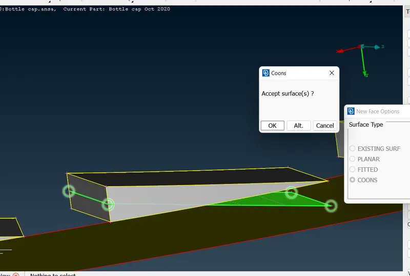
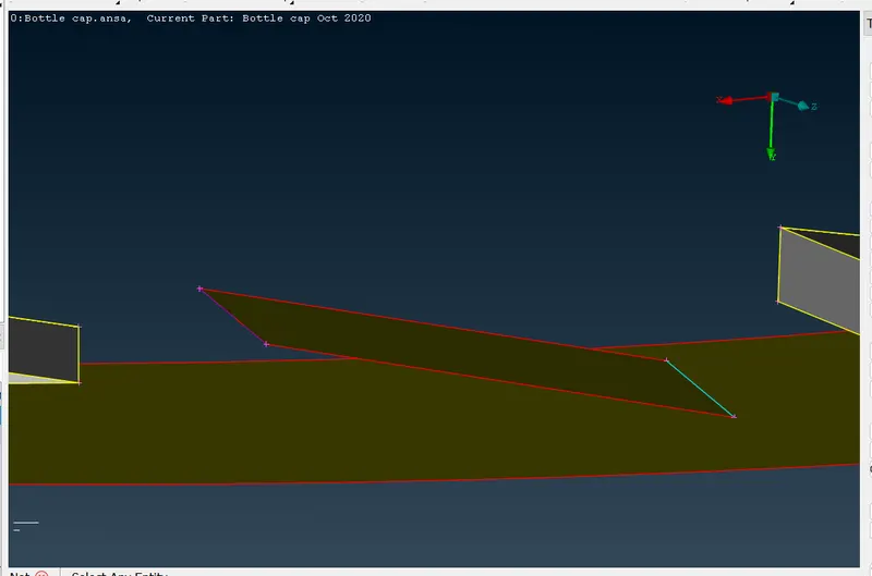
- But its onle for the one Tooths , There are total 26 same tooths on the same round surface , which are need to create .
- Same process for midsurface creation for the Tooths is time consuming .
- For lowering the time required , same Tooth midsurface can be Copied and transfer in rotating way .
- For rotating this midsurface , we need to create two points .
- This Points are created using the Two Circles at diffrent level .
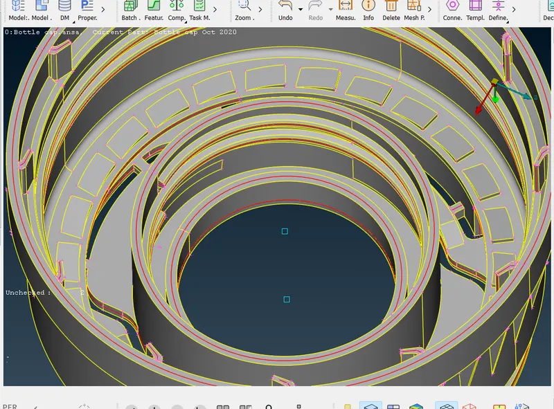
- This Two Points will acts as Axis of rotation for rotating the Tooths Midsurface .
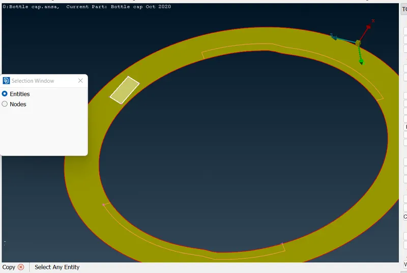
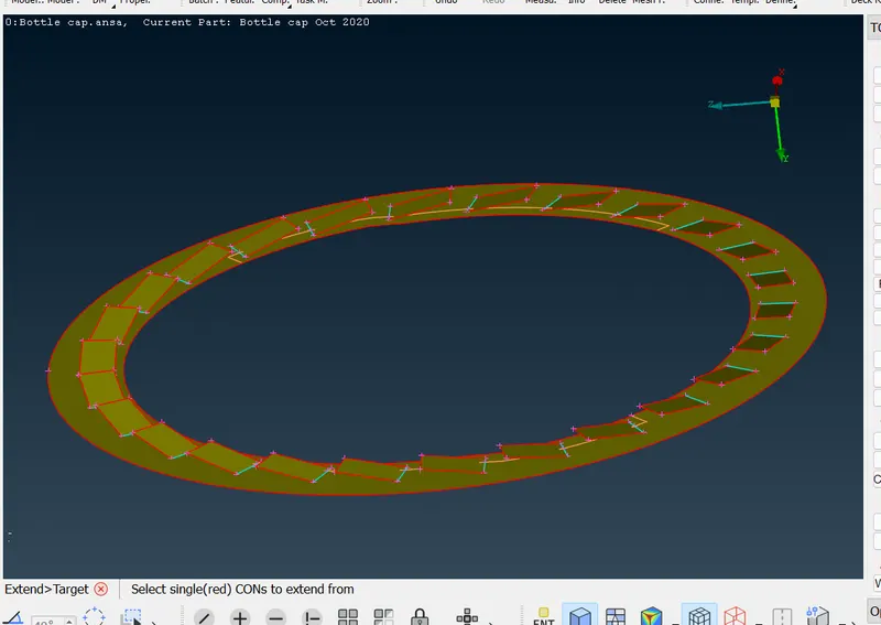
- Using the Transform Tool , This Tooths are copied and rotated in 360 degree on the Round parent surface .
- Using this Axis of rotaion , Tooth is rotated using the 25 Steps more and at an angle of 360/26 degree.
- Now for Middle fillet midsurface extraction , its thickness is measured by creating the spot weld and projecting it on opposite face which is 1.24 unit .
- Upper Face is the Offseted in the opposite direction of the Arrow at distance of 1.24/2 unit .
- Outside ribs Midsurface extraction is done by taking the middle of the Two side surfaces of the ribs using the Miidle Tool as ,
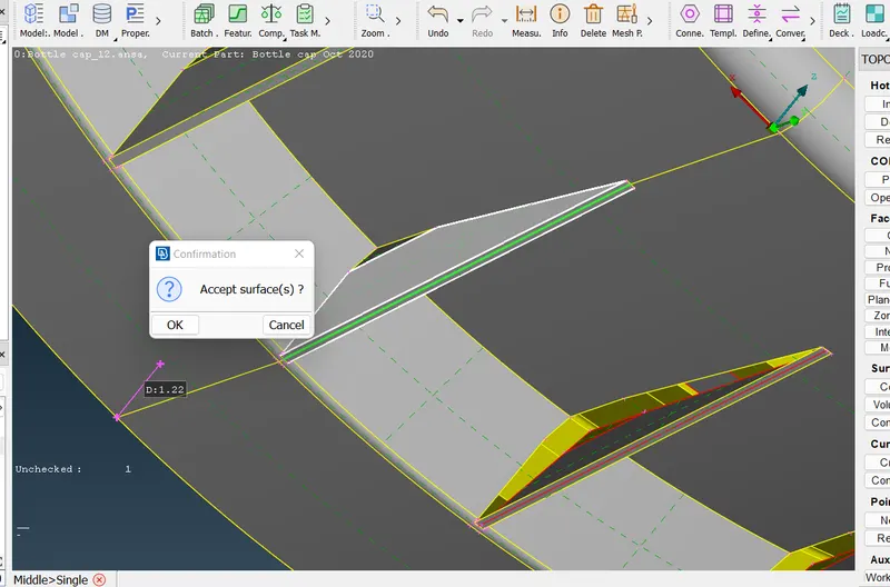
- This Tool creates the surface extact at the mid of the selected surface .
- Midsurface for all the Ribs are created in the same way .
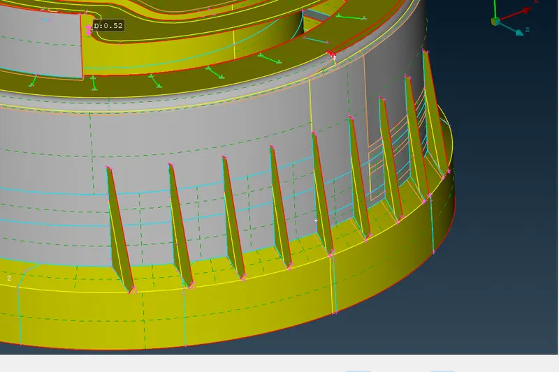
- Now at bottom there is region where element would fail for the minimum length .
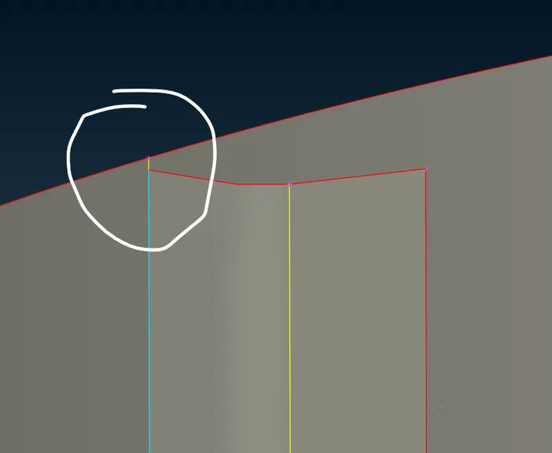
- For avoiding this minimum length elemental failure , in that region new surface is created equivalance to the fail minimum length of the element .
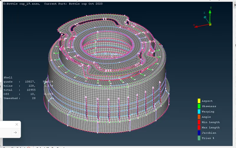
- Now after correcting and extracting the midsurface for all the Surfaces , Meshing is done with the Traget elemental length of the 1 unit and 0.5 unit , 3 unit for length range for minimum length and Maximum length respectively .
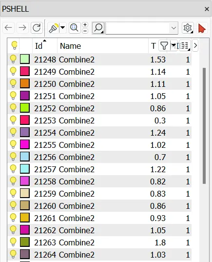
- Thickness is also assigned by creating the various properties with various Thickness as ,
Results :
Bottle Cap model with fully mesh Can be seen below as ,
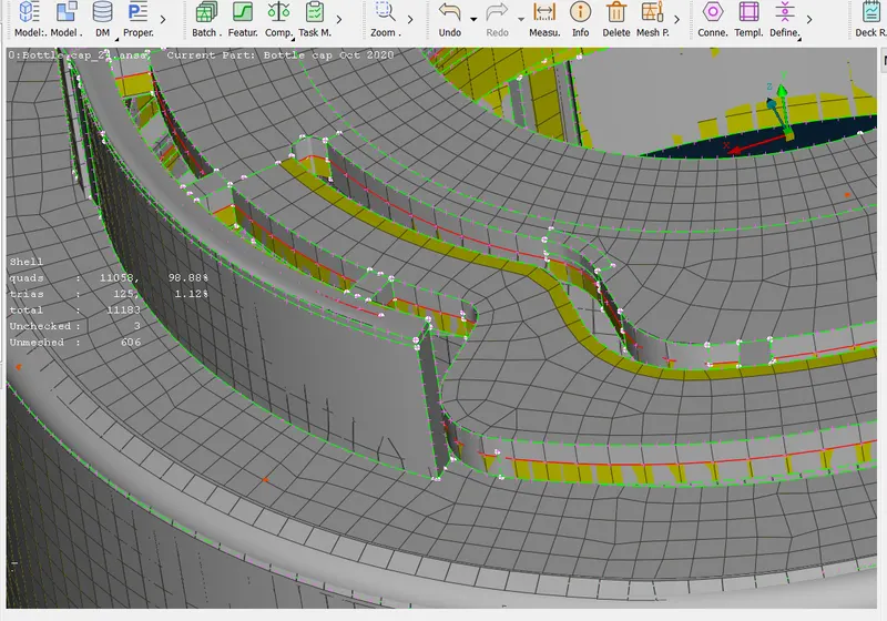
After assigning the Thickness properly to all the surface the model can be seen like below ,
Conclusion :
- For this Model the midsurface is extracted Manually as Auto midsurface wasn't giving proper surface .
- Midsurface is extracted for all the Surfaces using different Midsurface extraction Techniques like Middle Surface Tool , Offset Surface Tool , New Surfaces with Cons etc.
- Meshing is done with passing most of the elements with Quality criteria pass .
- Some elements are Failed for the Minimum length because of the less constrain .
- This Elements Can not be removed because of the two surface and triple Cons.
- Thickness is assigned to the model with proper thickness for all the Surfaces .
- The final Model is attached below .