Project
AIM:
To carry out system-level simulation of all-terrain vechicle.
THEORY:
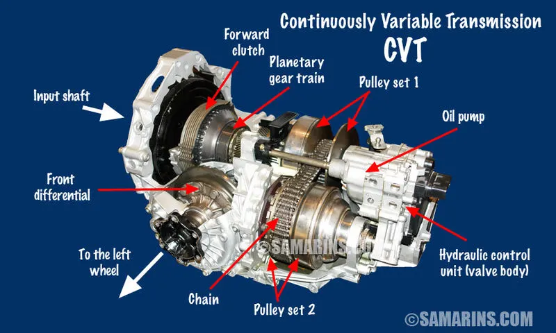
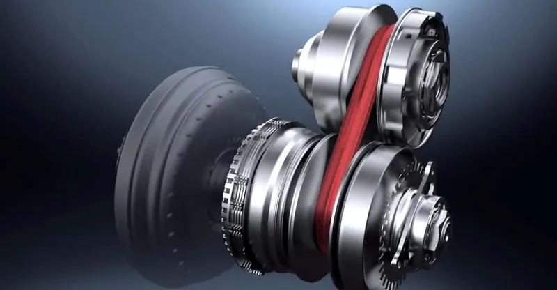
In the all terrain vechicle a CVT drive is use to transfere power to wheel from the engine. CVT stands for Control Variable Transmission. Unlike other mannual and automatic transmission which has set number of gears to achieve desire set gear ratio CVT does not have rather it has two coned shape pulley one is connected to engine and other one connected to the wheel. The cone shaped pulley is driven by a belt drive made up composite material which contains steel as major part to provide reinforcement tto the belt for high speed reliable performence.
The two pulleys can change their diameter which effects the gear ratio if the driving pulley diameter is less than the driven pulley then the outspeed at driving side is less and the input speed at driven side is high which results in reduction of gera ratio vice versa if the diameter of the driven gear is less than the driving gear which increases the speed ratio and high RPM is achieved at the wheels. The width of the pulleys changes depending on how much power the vehicle needs. When one pulley gets larger, the other one gets smaller. Since neither the pulleys or the belt are fixed.
Lower gear ratio gives high torque and lower speed or RPM and higher gear ratio gives lower torque and higher speed or RPM.
The advantage of the CVT is that it has infinite number of gear ratio compare to manual and other automatic drive system. One of the advantages of a CVT is its ability to continuously change it's gear ratio. This means that no matter what the engine speed is it is always performing at its peak efficiency CVT often offer better fuel economy as a result, especially when driving in the city.
- Image of CVT is given below.
WHAT IS AN ATV:
An all terrain vehicle ATV is defined as a motorized off highway vehicle designed to travel on four low pressure or non-pneumatic tires having a seat designed to be straddled by the operator and handlebars for steering control.
ATVs are subdivided into two types as designated by the manufacturer.
- Type I ATVs are intended by the manufacturer for use by a single operator and no passenger.
- Type II ATVs are intended by the manufacturer for use by an operator and a passenger and are equipped with a designated seating position behind the operator.
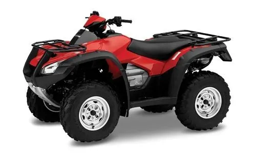
In this project we will study ATV model with CVT drive in MATLAB Simulink with different cases.
CASE 1:
STUDY 1: ATV WITH CVT MODEL
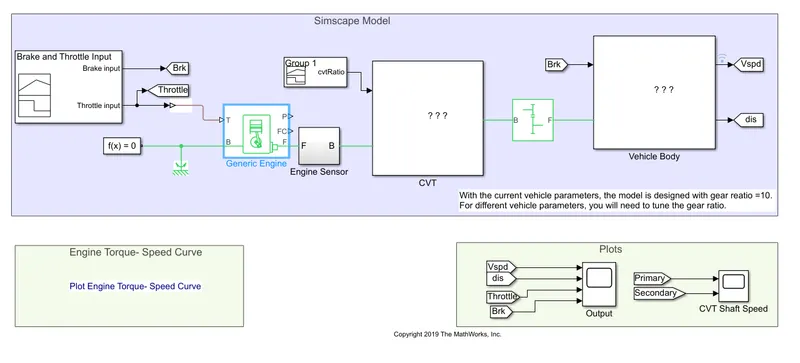
COMPONENTS USED:
- Generic Engine Block:
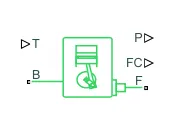
Represents a system-level model of spark-ignition and diesel engines suitable for use at initial stages of modeling when only the basic parameters are available. Optional idle speed and red line controllers are included.
The throttle input signal T lies between zero and one and specifies the torque demanded from the engine as a fraction of the maximum possible torque. If the engine speed falls below the Stall speed, the engine torque is blended to zero. If the engine speed exceeds the Maximum speed, the simulation stops and issues an error message.
Connections F and B are mechanical rotational conserving ports associated with the engine crankshaft and engine block, respectively. Connections P and FC are physical signal output ports through which engine power and fuel consumption rate are reported.
- Engine Sensor Sub system
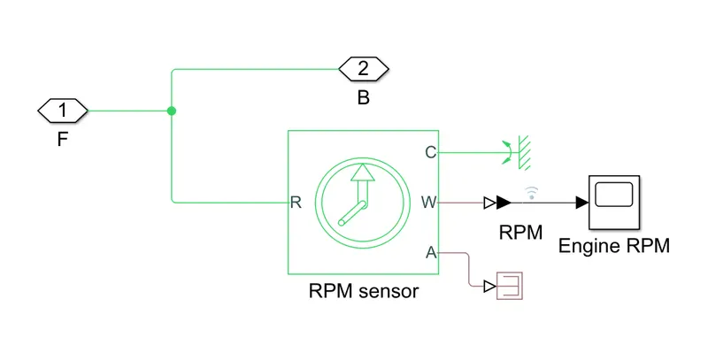
The Engine Sensor Sub System Block contains the above blocks it contains Ideal Rotational Motion Sensor and a scope. In the Ideal Rotational Motion Sensor port R and C are mechanical rotational conserving ports and connections W and A are physical signal output ports for velocity and angular displacement respectively. F is the input from the engine block and B is the output from Engine sensor which is RPM.
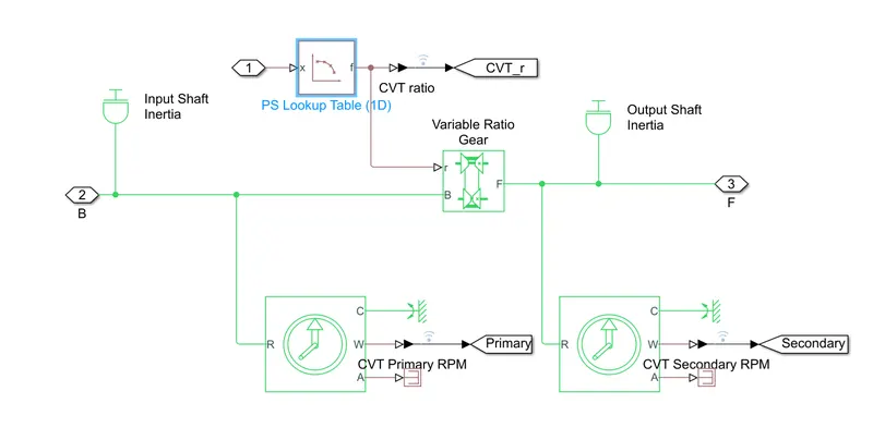
- CVT Ratio.
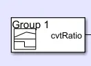
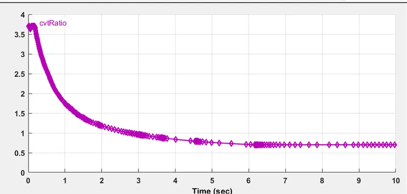
The CVT Ratio is actually the gear ratio in common terms, from the signal builder we can see there is a great range of gear ratio which is not possible in manual or other type of automatic drive system. This is the main advantage of CVT drive.
- CVT (Control Variable Transmssion)
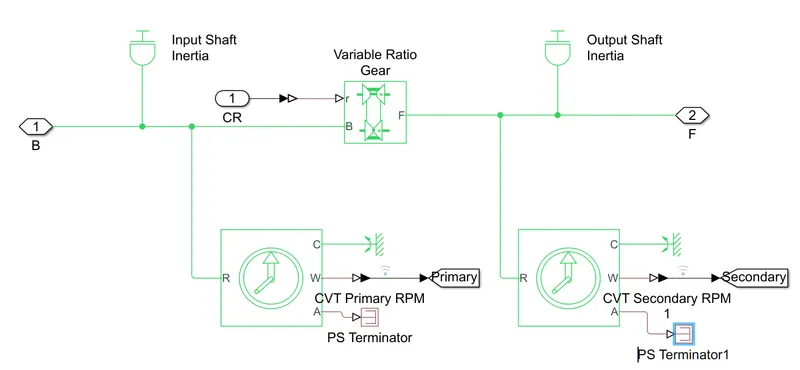
Input is coming from the engine sensor port B which is RPM and other input is coming from CVT ratio signal builder (CR) both are going into Variable Ratio Gear The physical signal input r defines the ratio of input to output angular shaft velocities.Connections B (base) and F (follower) are mechanical rotational conserving ports specify the relation between base and follower rotation directions with the Output shaft rotates parameter.
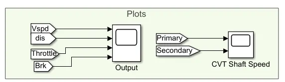
A Ideal Rotational Motion Sensor is connected to take the measure of input RPM to the CVT as CVT primary RPM and output RPM from CVT to wheels as CVT secondary RPM. A goto block is used with Ideal Rotational Motion Sensor to map it with to block outside subsystem with scope and take results of RPM shift by CVT.
- SIMPLE GEAR
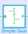
The output from CVT goes to simple gear. Represents a fixed-ratio gear or gear box. No inertia or compliance is modeled in this block. Connections B (base) and F (follower) are mechanical rotational conserving ports. Specify the relation between base and follower rotation directions with the Output shaft rotates parameter.
- VEHICLE BODY
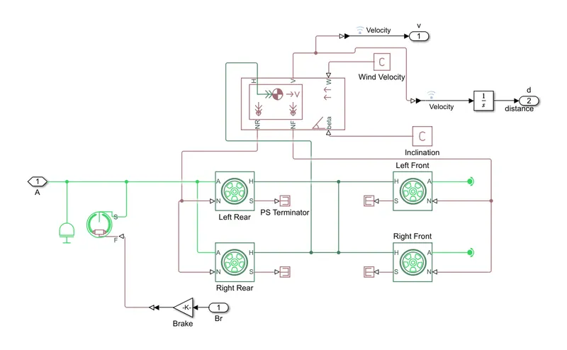
The input to this subsystem is Break signal from signal builder block and output from this block is Vspd(Vehicle speed) and dis (Displacement).
Vehicle Body Block - Represents a two-axle vehicle body in longitudinal motion. The block accounts for body mass, aerodynamic drag, road incline, and weight distribution between axles due to acceleration and road profile. The vehicle can have the same or a different number of wheels on each axle. Connection H is the mechanical translational conserving port associated with the horizontal motion of the vehicle body. The resulting traction motion developed by tires should be connected to this port. Connections V, NF, and NR are physical signal output ports for vehicle velocity and front and rear normal wheel forces, respectively. Wheel forces are considered positive if acting downwards. Connections W and beta are physical signal input ports corresponding to headwind speed and road inclination angle, respectively.
Inside the subsystem block Tire (Magic formula) block is used. It Represents the longitudinal behavior of a highway tire characterized by the tire Magic Formula. The block is built from Tire-Road Interaction (Magic Formula) and Simscape Foundation Library Wheel and Axle blocks. Optionally the effects of tire inertia, stiffness, and damping can be included.Connection A is the mechanical rotational conserving port for the wheel axle. Connection H is the mechanical translational conserving port for the wheel hub through which the thrust developed by the tire is applied to the vehicle. Connection N is a physical signal input port that applies the normal force acting on the tire. The force is considered positive if it acts downwards. Connection S is a physical signal output port that reports the tire slip which is connected to PS Terminator in this case.
- SIGNAL BUILDER - BRAKE THROTTLE INPUT
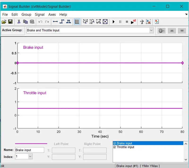
This signal builder provides Throttel Input to Generic Engine block and Brake input to Vehicle body. The throttle input is between 0 and 1 whereas brake input is 0.
RESULTS
- ENGINE TORQUE SPEED CURVE
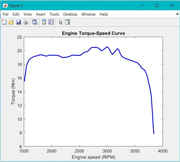
The torque is maximum at lower Rpm and least at highest RPM. The profile of torque achived is such because of CVT drive system as it has almost infinite Gear Rtaio.
- OUTPUT
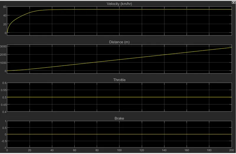
- The Output scope shows the graphs of Velocity in Km/hr, Distance in meter, Throttle and Brake.
- The velocity is increasing exponentialy at first and then it becomes constant because the throttle input is constant 0.5 but the velocity increase at intial stage due to CVT drive and when the lowest Gear ratio is achieved by the CVT for constant Throttle input the velocity gets constant at 55 KM/hr.
- The Distance plot shows that the distance is increasing linearly with respect to time.
- The Throttle input is constant at 0.5.
- The Brake input is 0.
CVT SHAFT SPEED
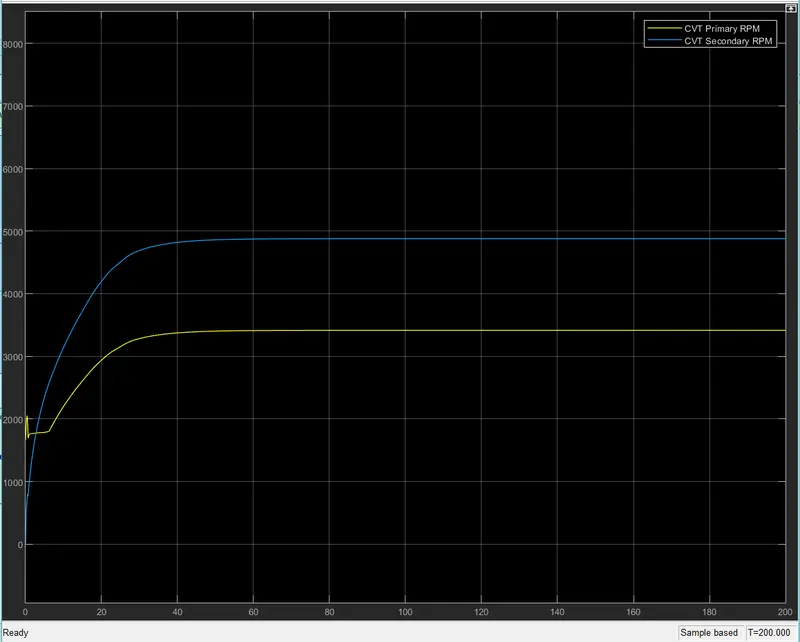
The CVT shaft speed shows the two RPM one that is given input to the CVT drive know as primary RPM represented by yellow color and the other that is the output RPM given by CVT to wheels via simpl Gear arrangement is represented by blue color.
The primary RPM start from around 1700 RPM but the secondary RPM starts from 0. The Exponential part of the graph is due the the CVT drive infinite Gear Ratio. The seconadry Rpm shows that how the CVT drive can easily step down the RPM and step up it smoothly.
CASE 1
STUDY 2 - ATV WITH CVT AND DASH BOARD
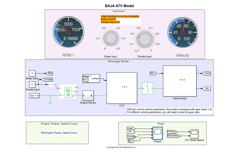
The above model is same as study 1 but the only difference is in this model we have a dashboard control where knobs are there to apply brake and throttle. The dials shows RPM and speed.
RESULTS
- ENGINE TORQUE SPEED CURVE
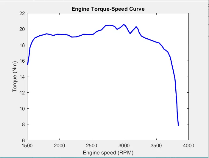
The torque is maximum at lower Rpm and least at highest RPM. The profile of torque achived is such because of CVT drive system as it has almost infinite Gear Rtaio.
- OUTPUT
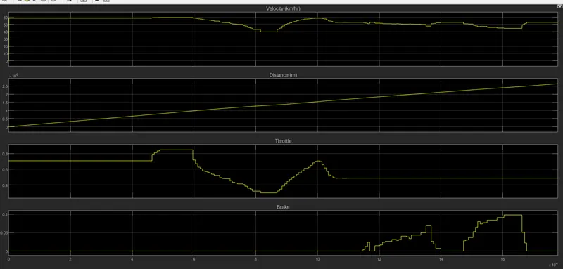
As the model has the knob controll for Brake and Throttle. The velocity, distance, Throttle and Brake outpust are different than the study 1 output ressults. They are varying in output due the inputs provided by knobs.
CASE 2 STUDY 1
BAJA ATV WITH LOOKUP TABLE
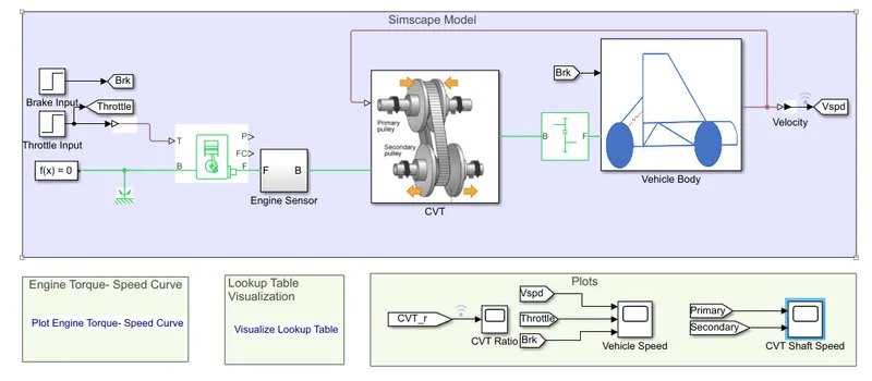
In this study step block is used as input for Brake and Throttle rather than Signal builder block in previous case 1. In this study lookup table is used for input the CVT ratio that is gear ratio. These are the input difference in between case 2 study 1 and case 1 study 1. Rest all are same.
RESULTS
- ENGINE TORQUE SPEED CURVE.
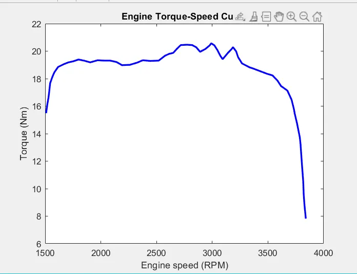
The torque is maximum at lower Rpm and least at highest RPM. The profile of torque achived is such because of CVT drive system as it has almost infinite Gear Rtaio.
- LOOKUP TABLE PLOT
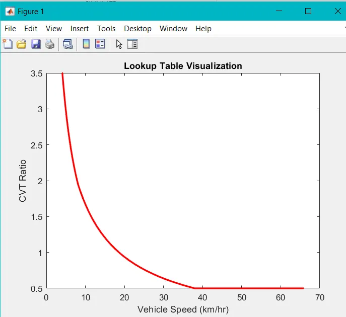
From the above image it is clear that for higher CVT ratio the vehicle speed is less and as the CVT ratio decreases vehicle speed increases which follows the rule of gear ratio.
- CVT RATIO
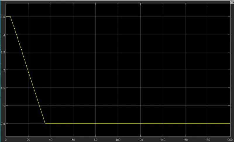
The above image shows how the CVT ratio changes with time and then become constant at 0.5.
- OUTPUT
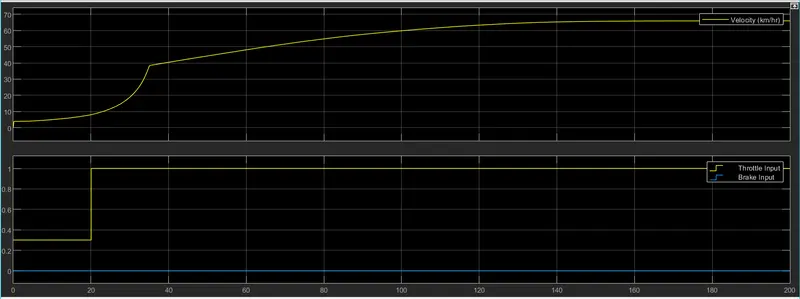
From the image we can see that the velocity increases according to the input provided by the lookup table for CVT ratio.
As the throttle input is provided by step block so it's range is from 0.3 to 1 and it can be seen from the graph above. The brake input is zero throughout the simulation.
- CVT SHAFT SPEED
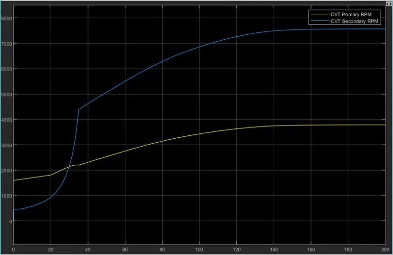
This graph show case how efficient the CVT drive is in stepping up and down the driving RPM.
CASE 2 STUDY 2
BAJA ATV WITH LOOKUP TABLE AND DASH BOARD CONTROLL
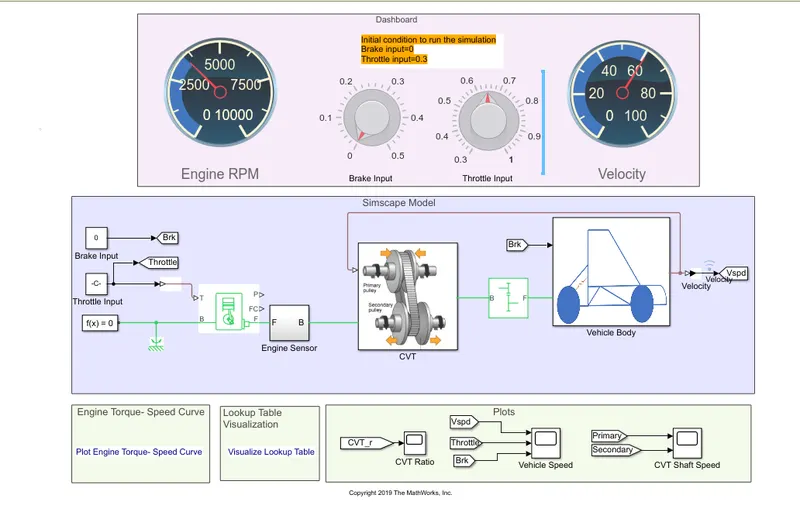
In this study every thing is same as case 2 study 1 only one extra element is added that is dash board controll with knobs and Dials knobs to controll Throttle and Brake and dials to show RPM and velocity obtained from the given inputs. Hence the results are affected by knob controlls.
RESULTS
- ENGINE TORQUE SPEED CURVE.
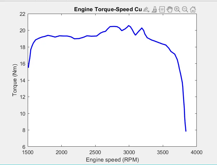
The torque is maximum at lower Rpm and least at highest RPM. The profile of torque achived is such because of CVT drive system as it has almost infinite Gear Rtaio.
- LOOKUP TABLE PLOT
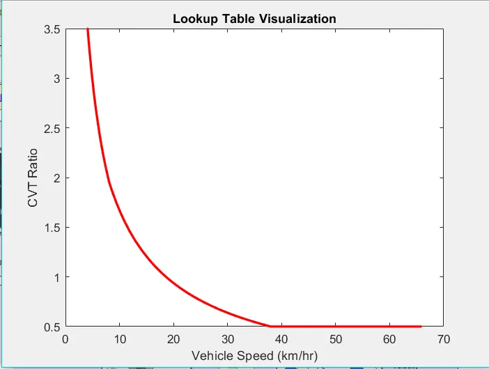
From the above image it is clear that for higher CVT ratio the vehicle speed is less and as the CVT ratio decreases vehicle speed increases which follows the rule of gear ratio.
- CVT RATIO
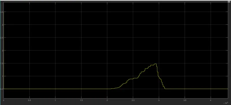
Due to Knob controll of Throttle and brake the graph is like this cause when the RPM goes down the CVT ratio goes up and vise versa.
- OUTPUT
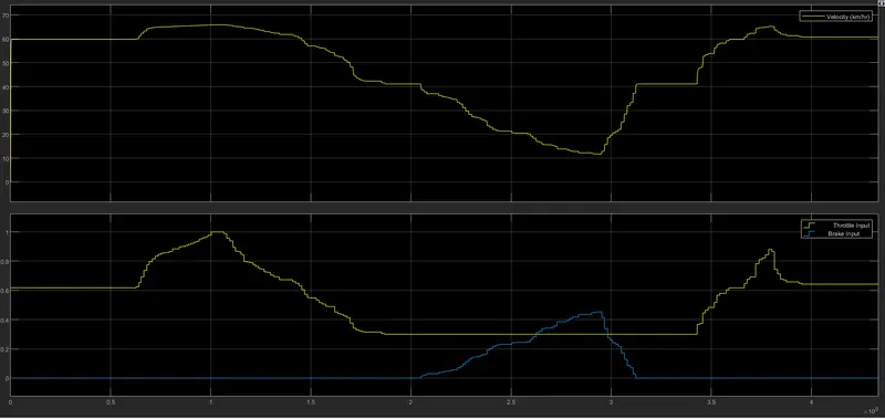
Due to Knob controll of Throttle and Brake velocity, Throttle and Brake shows variation and the same can be visualised from the above image.
- CVT SHAFT SPEED
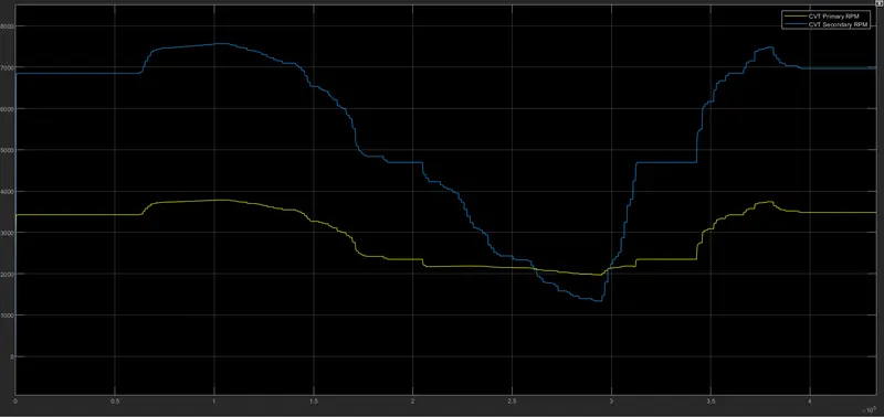
This graph show case how efficient the CVT drive is in stepping up and down the driving RPM. Due to Knob controll such variations can be seen in the graph of Primary and secondary CVT RPM.