Week - 4
Ans 1:
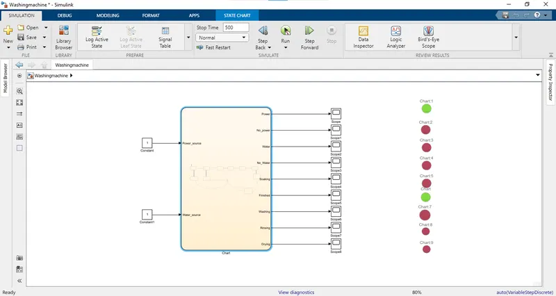
1) Following fig shows the Stateflow for the Washing Machine, using Simulink Statflow logic for the above metioned logic with given time period
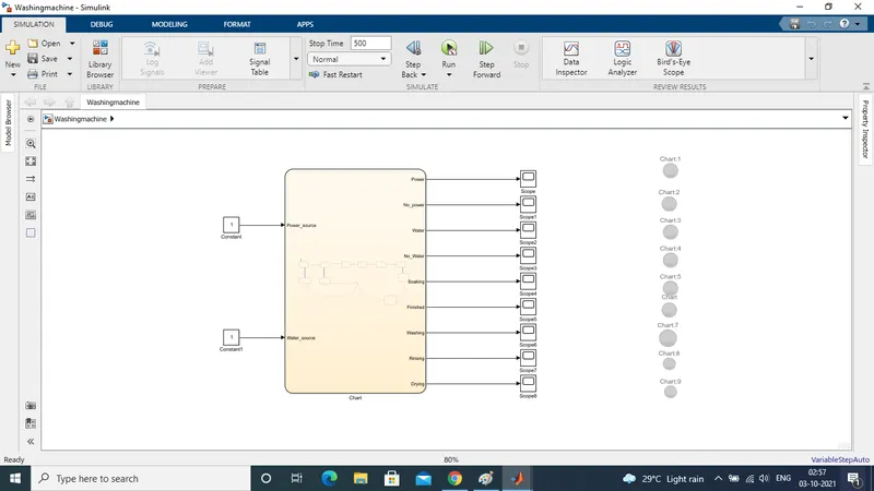
2) As shown in above model , the Input is given with "Constant " Block. two " constant" blocks are used for each one for the "Power_Source ", and "Water_Source"
3) Furhter, around 9 Ouput are used to show the ouput satisfactorily with different condition , the ouput are futher connected to repective scope which are further given to the "Lamp " to see the final states of ouput with Red or Green Light
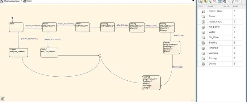
4) Following fig shows the "Chart" view of the above "Stateflow" logic with simulink
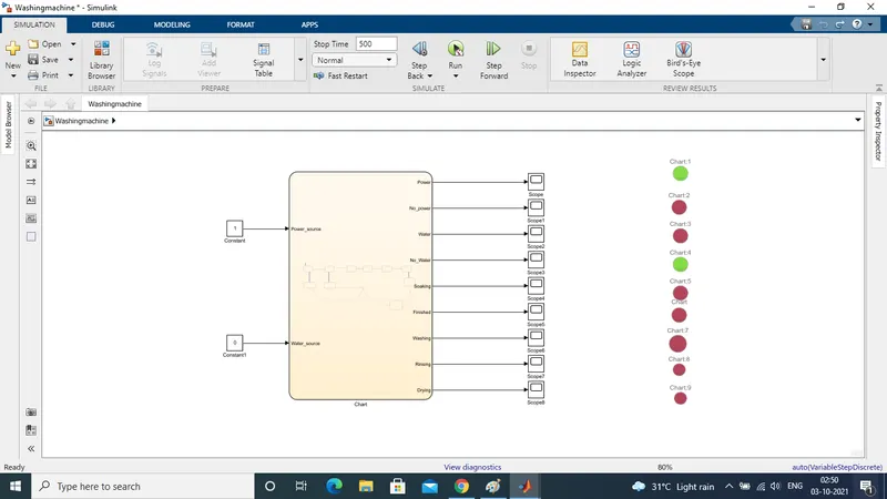
6) If the Power is on, But water supply is not availbae then Washing Machine should stop the process and should come to an end , following fig shows the result when power is On But the Water is Not available ( Cahrt 4-Lamp -Green -No water )
6) As shown in above stateflow , the Given condition are implemented after the repcetive time interval for the Soaking, washing , Rising and the Drying the seguenc followed is as below
1) If Power_ Source and Water_Source bothe are 1 (ON), then follows the below sequence
1) Go for the Soaking for 200 Sec
2) Go for the Washing for 100 Sec
3) Go for the Rinsing for 20 Sec
4) Go for the Drying for 50 Sec
5) Finshied the Task with Indication on the Repective Lamp
7) If the Power and Water both are available , then Washing Machine will follow all the option as mentioned after the Given time period and Will Finsihid the Task completely indicating same on the Repectvie LED (Finished - Chart 6 -Lamp) , Following fig shows the same
Ans 2 :
1) Following Fig shows the "Smulink Model for the Gear Shift "
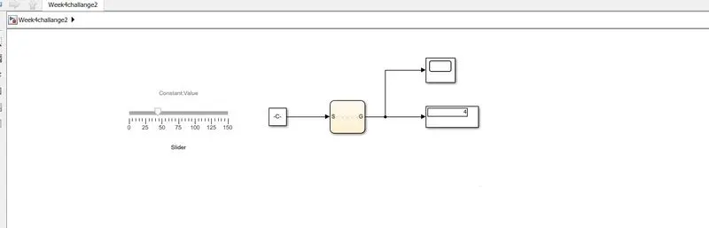
2) As shown in abov fig the "Slider " is used to give the Desired speed input to the "Chart" throgh the Constant
3) The following fig shows the "Chart " stateflow diagram for the Desired Gear shift for the Respective Speed input
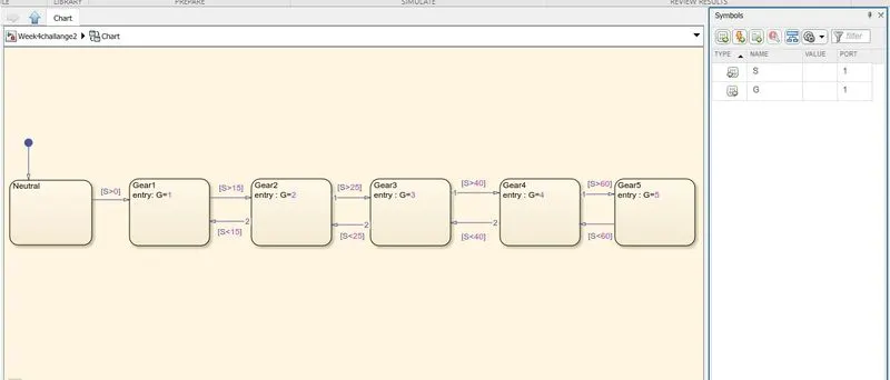
4) As shown above , the Input and Ouput are defined as S and G respectively , where S = Speed , and the G = Gear
5) The input stateflow condition are mentioned for each block as show in above to get the desired gear shift from the G =1 to 5
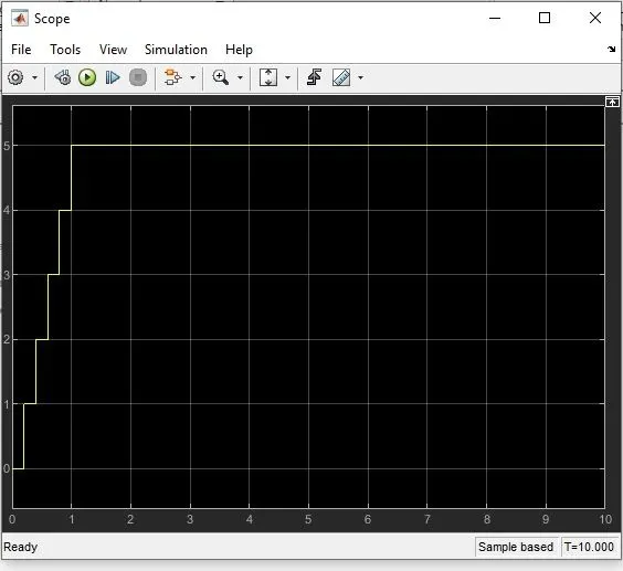
6) The following fig shows the Ouput of the scope for the Gear shift from 1 to 5