Week -2
Ans 1:
1) Following fig shows the Simulink Model of the solenoid block with above mentioned details
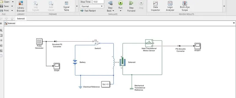
2) As shown in above block Diagram , The pulse generator is connected to the Switch Through the Simulink -PS Converter
3) The switch is further connected to the battery in series , along with Electrical part of the Solenoid
4) The "Block Parameter " of the Pulse Generator are changed as per the requirement of the model , following fig shows the "Block Parameter " of the Pulse Generator
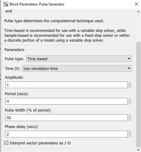
5) As shown in above , the Amplitude is kept equals to 1, and Period of the Pulse is kept equals to 4 sec , we want the Delay of 2 sec , so "Pulse Width " is set to 50% of the period
6) Following image shows the Actual Ouput from the "Pulse Generator " from the Scope connected
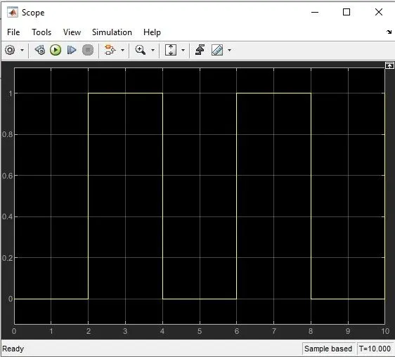
7) For the period when the Signal (Amplitude) from the Pulse generator is Zero , switch is not connected to the Battery and there is no any motion detected in the "Ideal Translation Motion sensor "
8) But when , the switch recives the signal for the rest of 2 sec from the Pulse Generator it gets coneected to the battery connecting solenoid in the circuit , which in turns connected to the "Motion sensor "
9) So for this period "Motion sensor " detects the Motion , which is further converted in to the "Simulink Signal " with help of the "PS to Simulink " Conveerter
10) Following fig shows the "Motion sensor " output through the Scope connected
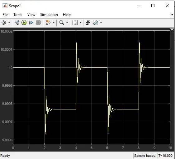
11) As shown in above Ouput , there is Motion detected after each interval of 2 sec which is being shown with help of "Damping " ,we can Reduce this Damping effect with help of "Damping " parameter of the Solenoid "Block Parameter " setting
Ans2:
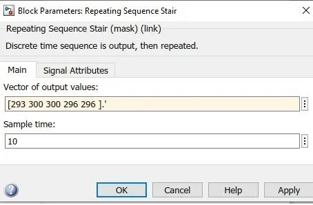
1) The given temperature conditons are implemented with "Repeating Sequence Stair " as below
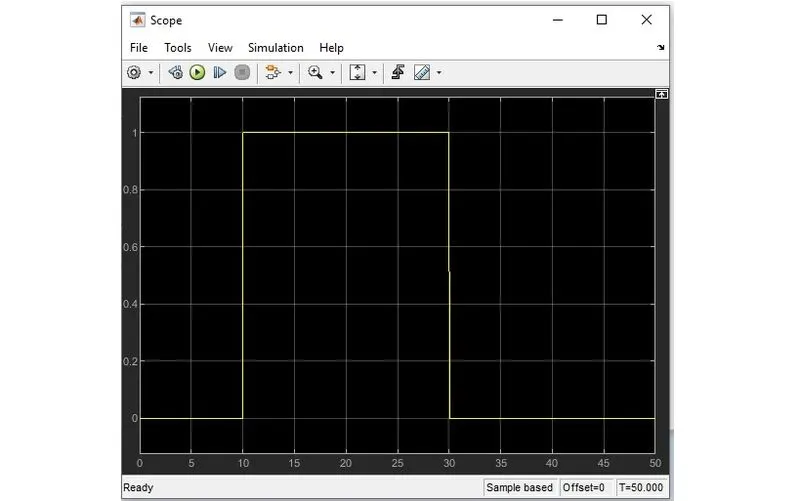
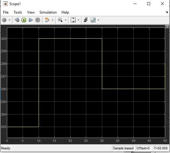
- For the time period t=0 sec to 10 sec , the T= 20 degree= 293 K
- For the time period t=10 sec to 30 sec, the T=27 degree = 300 K
- For the time period t= 30 sec to 50 sec , the T= 23 degree = 296 K
2) The Signal is generated with above conditon, with help of the "Repeating Sequence stair " by changing the input parameter inside the Paremeter Block , as shown below
3) The Ouput from the "Repeating Sequcne Stair " is applied to the "Temperature Controlled source ", and the same is analyse with Scope connected , following fig shows the Scope ouput
5) The Threshold voltage is measured for the Input Temperature of 25 degree(298K) , As we want the Fan (Lamp) to be ON for the Temprature more than 298K , and To be off for the Temperature less than 298 k
6) To measure the Thereshold voltage , The Single input ( 298 k ) is given to the "Repeating sequnce stair" with Same Sample time , the corrosponding voltage is measured across the Resistor
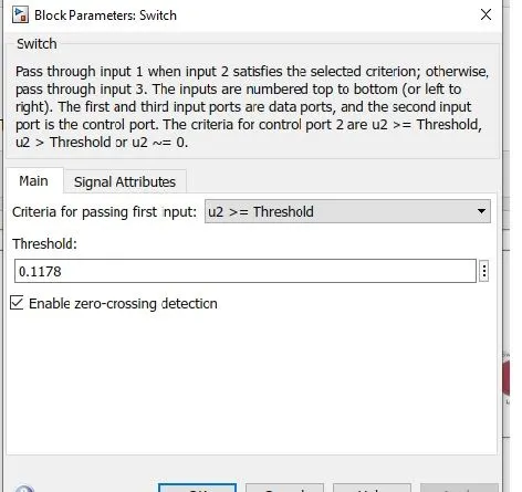
7) This Threshold voltage is then used to Decide the Input to the Switch , for the Voltage More than Threshold voltage the "Contant 1" is given as Input , and for the Voltage less than Threshold voltage "Constant 0 " is given as input to the Switch
8) Following Fig shows the "Threshold Voltage " apllied to the Switch
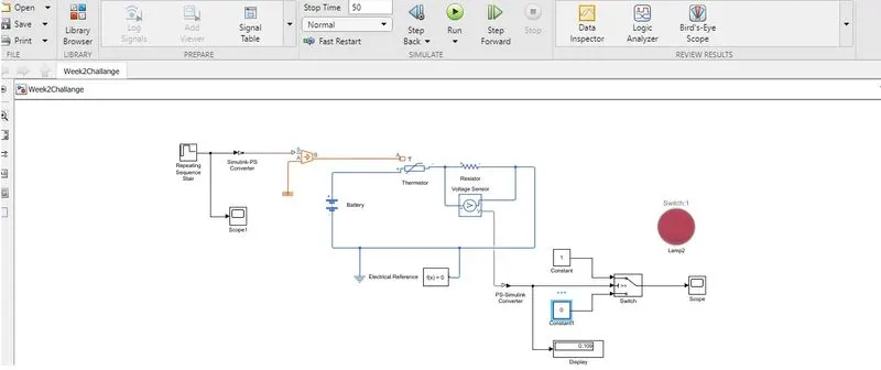
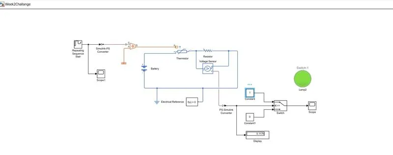
9) The output of the switch is further given to the Lamp and the Scope , According to the ouput of the Switch , the Lamp is Made ON(Green ) and OFF(Red )
10 ) For the Time period( t= 10sec to 30 sec) , when the Thereshold voltage is above ( 0.1178) The Lamp becomes Green(ON) and for the rest of the Time period , when the Therehold Voltage is below (0.1178) the Lamp remain Red (OFF)
Condition 1: When Temperature Below 298k( 25 Degree Celsius )
Condition 2: When Temperature is Above 298K(25 Degree Celsius )
11) Following fig shows the Final scope ouput , showing the states of Switch Ouput