Week - 4
Aim:-
- To impliment control logic of a "Washing Machine" using Stateflow for the given sequence.
- If the power supply is available ,the system gets activated.
- If the water supply is not available,stop the process & indicate through LED.
- Soaking time should be 200s followed by washing time of 100s.
- Then rinsing happens for next 20s & dryer runs for 50s.
After all the processes have completed turn on the finished LED.
2. Make a Simulink chart for the "Gear shift" logic as per below conditions:
Speed Range(KmPh) Gear
| 0 to 15 | 1 |
| 16 to 25 | 2 |
| 26 to 40 | 3 |
| 41 to 60 | 4 |
| Above 61 | 5 |
Give speed input while the simulation is running & display the gear nu.
- Block used:-
1) Slider Switch 2)Constant 3)Chart 4)Display 5)Lamp
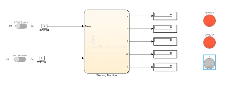
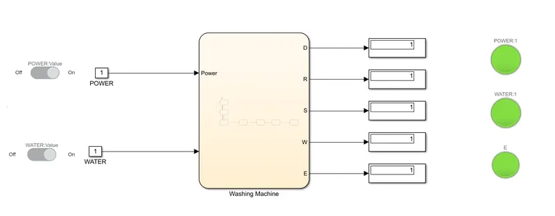
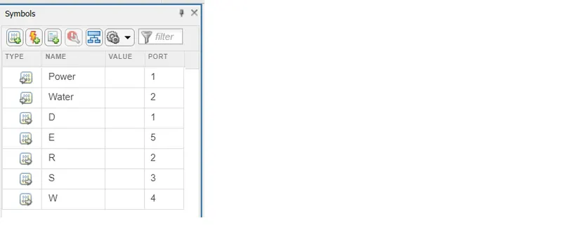
- Power and Water are given as a Input.
- D,R,S,W & E are given as a Output.
- MODEL AND STATEFLOW OF WASHING MACHINE:-
Explaination:-
1) Power & Switch inputs were controlled by the Switch block
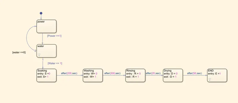
2) State blocks were used inside the chart to create a stateflowaccording to que.
3) The power input is get as Input in the chart & directed to the POWER state from there,if power = 1(means power supply is ON),it is directed to the next Water block or if (supply= 0) i. e. OFF, then it is directed to the junction.
4) Next State is water & from that if Water == 1(Water supply is ON) or if Water supply ==0 (Water supply is OFF) then it is directed to junction.
5)Then next is Soaking State, Entry=0, while exit is LED to to make it glow which is connected to this state.
6) After 200Sec, it is directed to Washing state, & after 100Sec, it is directed to Rinsing state & after 20Sec, it comes to drying state for 50 Sec & finaly it comes to END state.
- If power supply is ON, the system gets activated. If the water supply is not available ,Stop the process & indicate through LED.
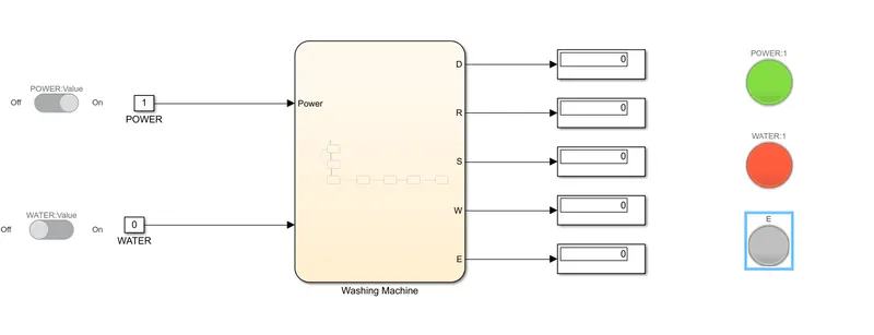
- When Water supply is given as ON i.e. = 1
- Symbol Pane:-
2) Make a simulink chart for the "Gear shift"
Speed Range Gear
| 0 to 15 | 1 |
| 16 to 25 | 2 |
| 26 to 40 | 3 |
| 41 to 60 | 4 |
| Above 61 | 5 |
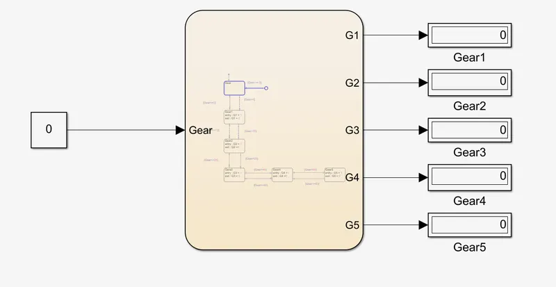
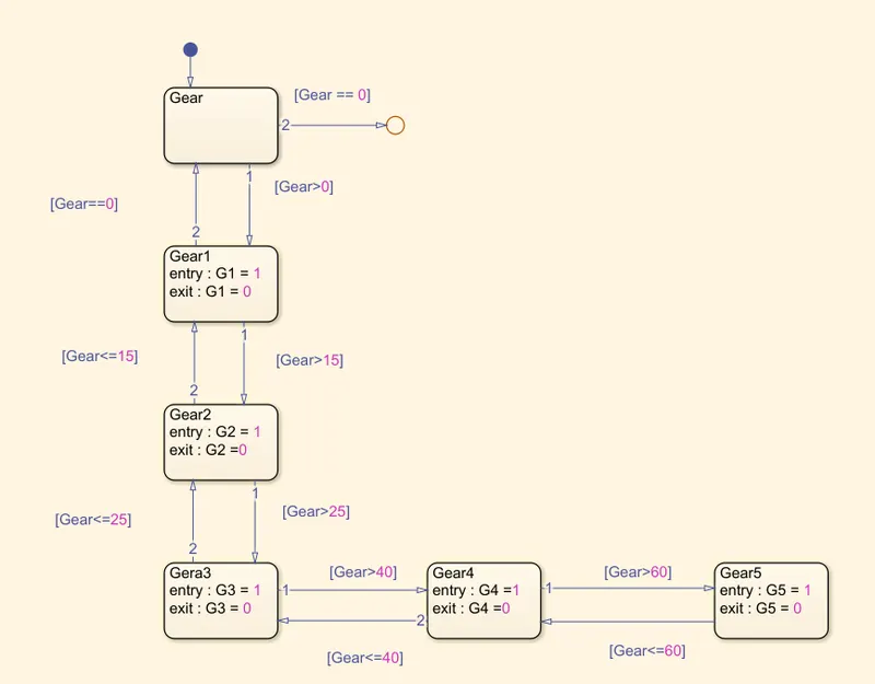
- MODEL & STATEFLOW OF GEAR SYSTEM:-
- SYMBOL PANE:-
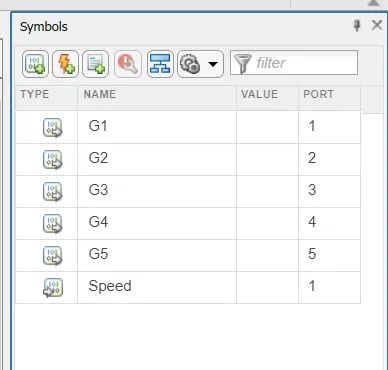
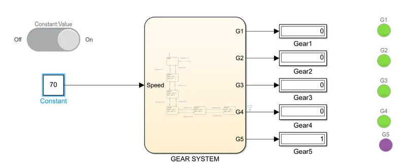
Speed is given as Input & G1,G2,G3,G4 & G5 are given as Output.
- Blocks Used:-
| 1)Slider |
| 2)Constant |
| 3)Chart |
| 4)Display |
| 5)Lamp |
- Explaination:-
1)Using the Slider block the inputs are varied by the user during the run-time & it is connected to Constant block.
2)This varying input values were given to the chart fromm cont. blocks.
3)State blocks were used inside the chart to get a conditioned state flow.
4)First the input values are generated to the Gear_shift block, from there according to condition ,Gear >0 it proceeds to the next state if not like Gear == 0 it ends the flow junction.
5)If Gear >0 it moves to GEAR1 state & when the input values crosses 15,it moves to next state.
6)If Gear>15 it moves to the Gear2 state & if Gear>25 it moves to Gear3 state.
7)If Gear>40 it moves to the Gear4 state & if Gear >60 it moves to the Gear5 state, & lamp is connected with each gear output.While entering the state lamp glows & while exiting the state lamp goes OFF.
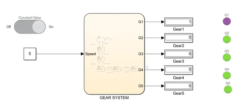
8)I have set 'PURPLE' colour for 'Lamp On',i.e. for active state of Gear
9)A Display block is connectd with each gear output to get the value of 0 or 1, which denotes whether the gear is in active state & according to this, lamp glows ON & OFF.
10)I have gievn stop time as 5Sec & run the model.
- ACTIVE STATE OF 1ST GEAR:-
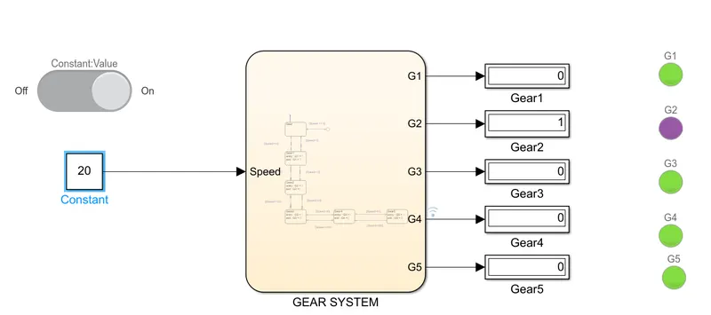
- ACTIVE STATE OF 2ND GEAR:-
- As speed input is above 15, it shifts to the second gear & lamp will Glow (ON), & rest are in OFF state.
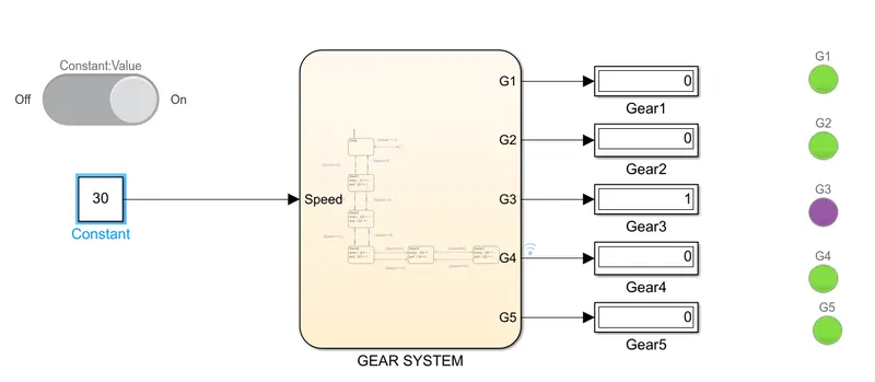
- ACTIVE STATE OF 3rd GEAR:-
- As speed increases more than 25, it shifts to 3rd Gear.
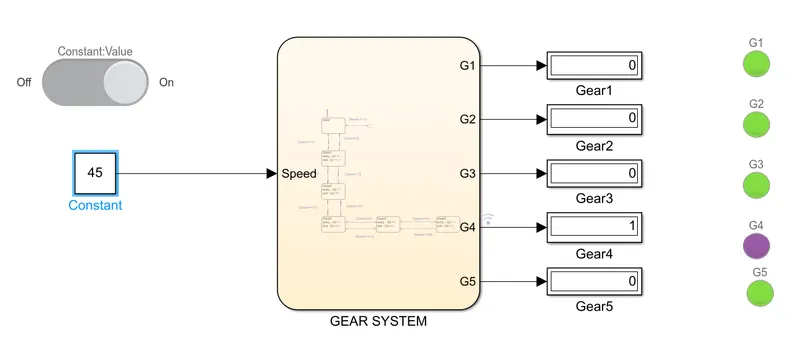
- ACTIVE STATE OF 4th GEAR:-
- As the speed increases more than 40, it shifts to 4th Gear.
- ACTIVE STATE OF 5th GEAR:-
- As the speed incerases above 61, it will shift to 5th Gear.