Week - 4
Aim:-
1. To implement control logic of a "washing machine" using Stateflow.
2. To make a Simulink chart for the "Gear Shift" logic
Washing Machine
Objective:-
1)Implement control logic of a “washing machine” using Stateflow
2)Soaking time should be 200s followed by a Washing time of 100s Then rinsing happens for the next 20s & dryer runs for 50s.
3)Process has to be indicated by the lights.
Simulink Model:-
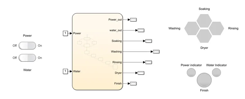
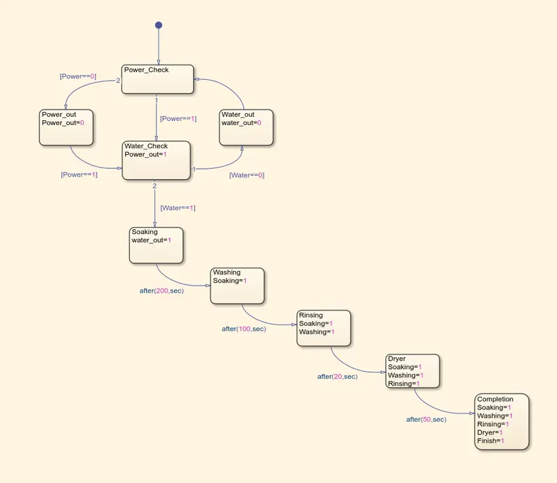
Explanation:-
-the control logic was was build with an initial condition for power supply such that when the value is ==1("==1" is when power is available and "==0" when power is absent) the path to the next block will open otherwise it will be redirected to the initial block.
-When the signal passes the power supply condition it reaches the water conditions in a similar manner as power condition when the water is available the condition will be satisfied or else it will go back to the initial condition.
-after bypassing the power and water condition the signal will go through the four condition blocks Socking, Washing, Rinsing, and Dryer with a respective time of 200,100,20, and 50 seconds.
-After each completion of each block the LED will be lit up representing the completion of the process or else the warning.
Result:-
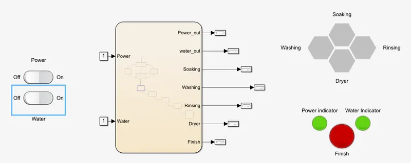
When the power connection is turned off.
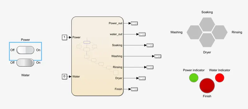
When the water connection is Turned off.
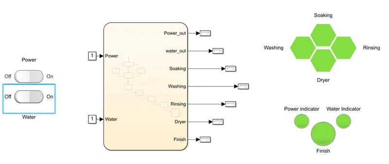
When the process successfully completed.
Gear Shift
Objective:-
-To make a Simulink chart for the "Gear Shift".
-Speed Range(kmph) Gear
0 to 15 1
16 to 25 2
26 to 40 3
41 to 60 4
Above 61 5
Simulink Model:-
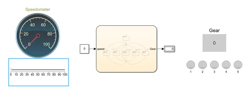
Explanation:-
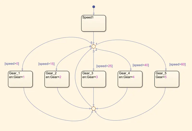
-The control logic was built depending on the value "speed" Depending on the value the signal will be diverted onto the respective block after satisfying the speed condition of the block.
-Each block is assigned a unique Block value Depending on the value of the speed the signal will be diverted to the block and depending upon the respective Block value the display will represent the Gear number and lit the respective LED.
Note: For faster Response of the system the block were connected parallel instead of series connection.
Result:-
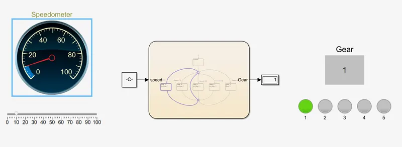
The system when running at 10kmph.
Gear engaged 1st.
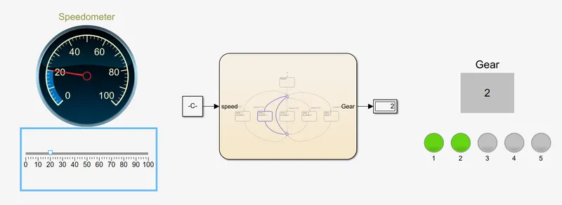
The system when running at 20kmph.
Gear engaged 2nd.
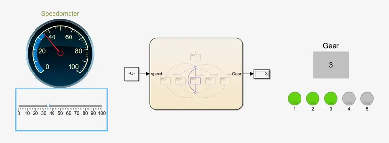
The system when running at 35kmph.
Gear engaged 3rd.
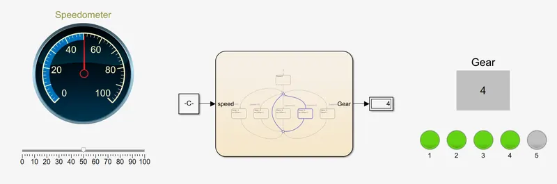
The system when running at 50kmph.
Gear engaged 4th.
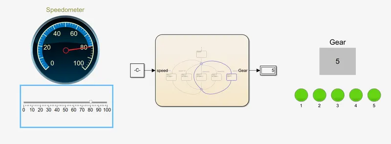
The system when running at 80kmph.
Gear engaged 5th.
Hence using the Stateflow and implementing the control logic of the "washing machine" and "Gear shift system" Simulink model was build and Simulated successfully.