Week -2
AIM:-
-To make a Simulink model of doorbell using solenoid block.
-By using a thermistor to sense the temperature of a heater & turn on or turn off the fan.
Doorbell
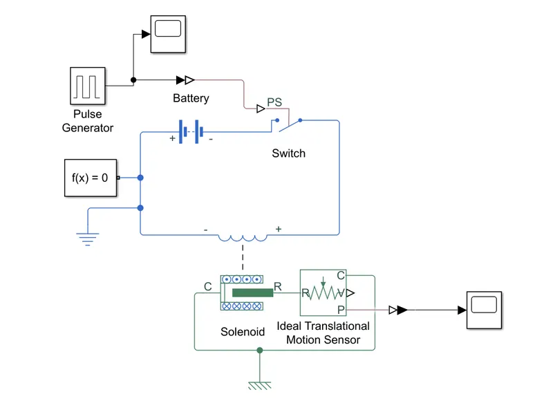
Objective:- To create a Simulink model of a doorbell which simulate the motion of the arm hitting the bell with a 2-sec interval between each hit
Simulink Model:-
Explanation:-
-Using a pulse generator we generate a pulse of 4 sec period with 50% pulse width with an amplitude of 1 unit then using Simulink-PS converter we converted the values to physical values.
-Then we construct a closed circuit consisting of the switch, solenoid, Electrical reference, solver configuration, and battery.
-By using the solenoid we convert the electrical signals to mechanical movement and using an Ideal Translation motion sensor we read the mechanical movement occurring at the solenoid.
-using Mechanical Translation Reference we ground the Solenoid and the Ideal Translation motion sensor.
Graph:-
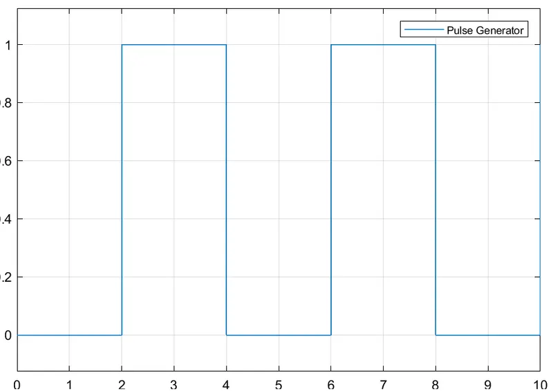
Figure 1:- Graph showing the signal input.
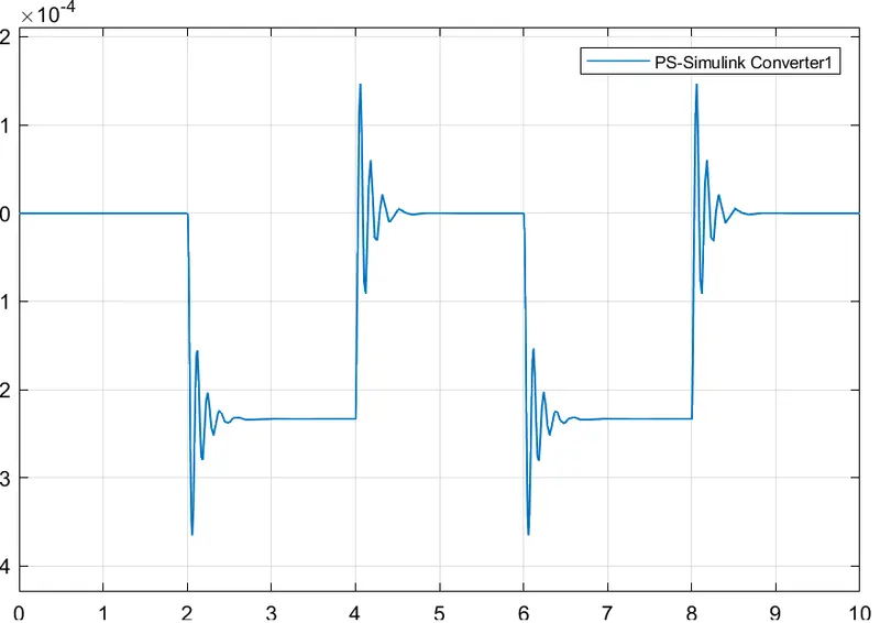
Figure 2:- Graph showing the signal output from the solenoid.
Result:-
Hence a Simulink model was created that represents the motion of the doorbell arm hitting the bell with a 2-sec interval between each hit.
Auto cut-off
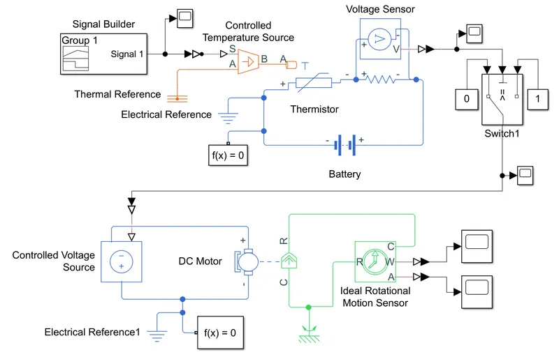
Objective:- To create a Simulink model to turn the fan on & off depending on the temperature of the heater using the thermistor.
Simulink model:-
Explanation:-
-Using the signal builder to build a temperature condition as given in the situation(i.e. 20 °C from 0 to 10 seconds, 27 °C from 10 to 30 seconds, 23 °C from 30 to 50 seconds) and connected to a scope to read the outputs. and used the Simulink-PS to convert the value to thermal values.
-Then we used the Control Temperature source to maintain a controlled temperature difference which is connected with the thermal reference and then the connection is connected to the Thermistor which converts the thermal values into the electrical values.
-The Thermistor is connected in a closed-loop consisting of resistance, Voltage Sensor, battery, Solver configuration, and electrical reference. When the condition is run the voltage from the voltage sensor is notes down using the scope.
-From the value record in the scope we set the upper limit of the threshold for the temperature at the switch to turn the switch on or off depending on the situation.
-Depending on the voltage value the switch sends the values to the Controlled Voltage reference which then convert the value into the electrical source which then turns the DC motor on or if the threshold value isn't cross the DC motor remains off.
-The RPM of the motor is recorded using the ideal rotational motion sensor which is grounded by using a Mechanical rotational reference and the value was noted using the scope block.
Graph:-
Figure 1:-the temperature condition built for 50sec
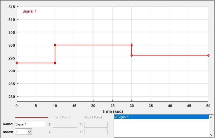
Figure 2:-The values Checked using the Scope block
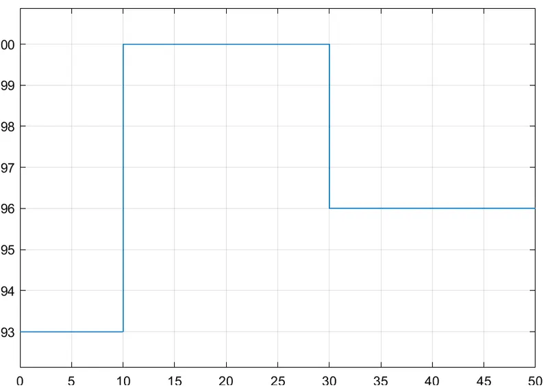
Figure 3:-Voltage values were recorded from the Voltage sensor
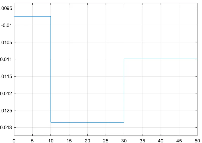
Figure 4:-After Setting the Threshold of -0.012unit Values were recorded to check whether the switching activating the circuit at the right condition
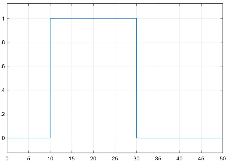
Figure 5:-The Switch was activating the circuit at the required condition
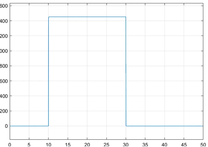
Hence the motor activated at the required duration of time
Result:-
hence the Simulink model to activate the fan at a given threshold was made.