Week - 4
AIM:
To Implement control logic and stateflow chart of a “washing machine” and “Gear shift” logic using Simulink.
OBJECTIVES:
- To Implement control logic of a “washing machine” as per the given set of instructions.
- If the power supply is available, the system gets activated, otherwise deactivated.
- If the Water supply is not available, stop the process & indicate through LED.
- Soaking time should be 200s followed by Washing time of 100s.
- Then rinsing happens for next 20s & dryer runs for 50s. After all the processes have completed turn on the finished LED.
- Make a Simulink chart for the “Gear Shift” logic as per the given conditions and Give speed input while the simulation is running & display the gear number as output.
|
Speed range (kmph) |
Gear Number |
|
0-15 |
1 |
|
16-25 |
2 |
|
26-40 |
3 |
|
41-60 |
4 |
|
Above 60 |
5 |
THEORY:
Stateflow
It provides a graphical language that includes state transition diagrams, flow charts, state transition tables and truth tables. We can also use stateflow to describe how MATLAB algorithms and Simulink models react to inputs signals, events and time-based conditions.
Stateflow enables us to design and develop supervisory control, task scheduling, fault management, communication protocols, user interface and hybrid systems. We can model combinatorial and sequential decision logic that can be simulated as a block with in the Simulink model or executed as an object in MATLAB.
Control logic
Control logic is the part of controller that defines how a reactive system responds to events on conditional changes.
Common tasks for modelling control logic includes:
- We can add flow charts to define complex control logic.
- Modelling hierarchical state machines for large scale systems.
- Defining orthogonal states to represent systems with parallelism.
- To Implement control logic of a “washing machine” as per the given set of instructions.
Washing Machine:
Washing Machine is a machine that washes dirty cloths, where the barrel is filled with water, and then rotated very quickly to make the water remove dirty from the cloths. Mostly washing machines are made so, that detergent (liquid or powders) can be put into the machine. These detergent makes the cloths clean.
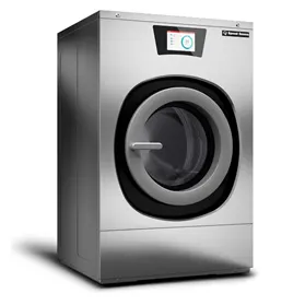
Different types of washing machines
- Front load washing machines: A front load washing machine is fully-automated washing machine that loads from the front side. These machines usually consume less water and energy, and usually yield better laundry results than top load counterparts.
- Top load washing machines: It is both manual and fully-automated washing machines come in a top form. These kinds of machines are loaded from the top. This is good for people who want a machine in which they don’t need to bend down completely to load the cloths in the machine. Fully-automated top load washing machines usually take up less space, so they are good for people looking to fit a washing machine into a narrow space.
- Fully-automated washing machines: A fully-automated washing machine does everything at the touch of a button. This washing machine comes with a single tub that acts as a washer, dryer and also rinses the cloths. These can come as front and top load machines, and the programs and efficiency can also vary between the machines, depending on the brand.
- Semi-automated washing machines: Unlike fully-automated washing machine, semi-automated washing machines are only partially automatic washing machines. This means that you will need to do some parts manually, like fill up the water in the tub before starting the machine, or if you have a twin-tub semi-automated washing machine, you will need to move the washed cloths into the drying tub. These are always going to be top loading.
Process chart of Washing Machine
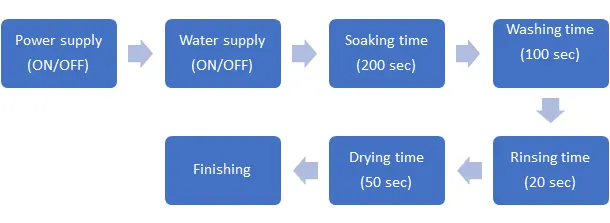
Procedure to construct the control logic
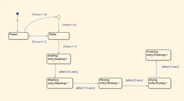
- On the Simulink interface, create an ‘chart’ block to define the stateflow as per given conditions.
- Inside the chart block, add junction block to terminate the signal flow and to return the null value.
- When the power is OFF, value (0) the process is terminated at the junction else 1 is carried forward.
- When the water is OFF, value (0) the process is terminated at the junction else 1 is carried forward.
- Then we have to activate the Soaking block, where the Soaking takes place for 200 seconds.
- After 200 seconds, washing block gets activated and washing takes place for 100 seconds.
- After 100 seconds, rinsing block gets activated and rinsing takes place for 20 seconds.
- After 20 seconds, drying block gets activated and drying takes place for 50 seconds.
- After 50 seconds, finish block will be activated and terminates the signal flow and ends the chart.
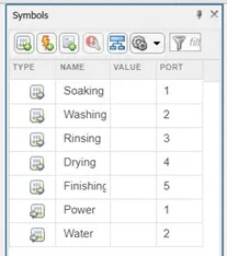
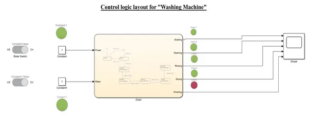
- In this stateflow chart, we have to give the power and water supply as input symbols and Soaking, washing, rinsing, drying and finishing as output symbols.
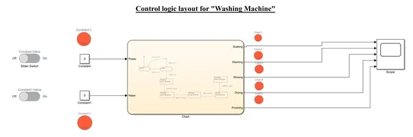
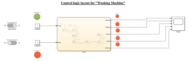
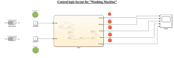
- Two separate constant blocks are connected to power and water supply as inputs. These constant blocks are connected to sliding switches to ON/OFF the power and water supply. When the value is ‘0’ the sliding switch if ‘OFF’ and when the value is ‘1’ the sliding switch if ‘ON’.
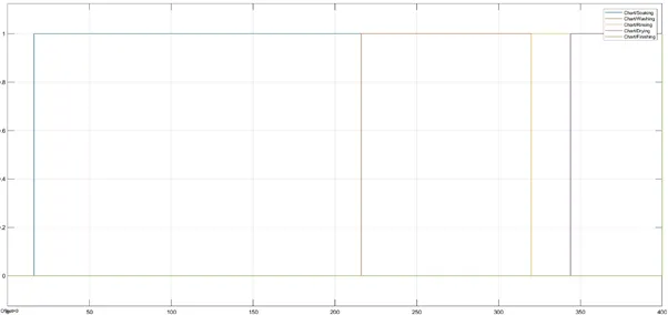
- The outputs from the chart block is connected to a common scope block to obtain the final results and the finish process is indicated by brown coloured lamp.
Stateflow
Symbols (Inputs/Outputs)
Power – OFF; Water – OFF
Power – ON; Water – OFF
Power – ON; Water – ON; Time = 0 sec
Power – ON; Water – ON; Time = 10 sec; Soaking – ON
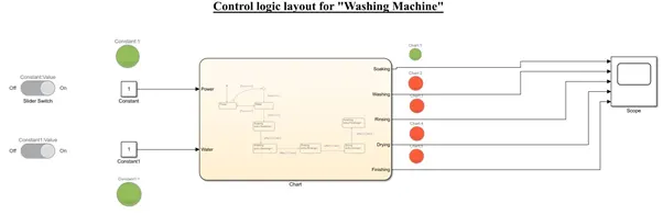
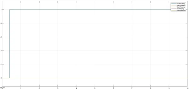
Power – ON; Water - ON; Time = 220 sec; Washing – ON
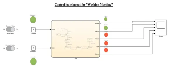
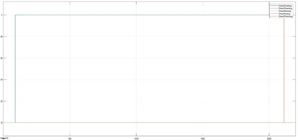
Power – ON; Water - ON; Time = 320 sec; Rinsing – ON
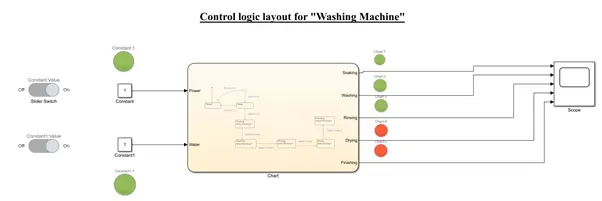
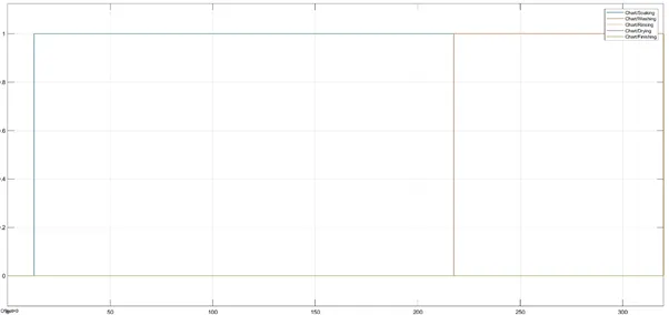
Power – ON; Water - ON; Time = 340 sec; Drying – ON
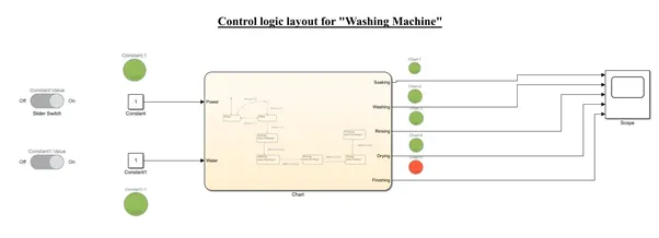
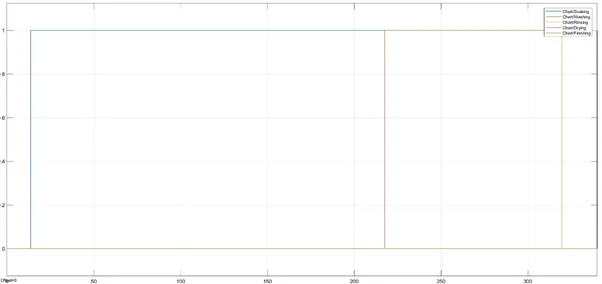
Power – ON; Water- ON; Time = 400 sec; Finished
Final Results
|
Steps |
Power supply ON/OFF |
Water supply ON/OFF |
Process |
Time (sec) |
|
1 |
OFF |
OFF |
- |
- |
|
2 |
ON |
OFF |
- |
- |
|
3 |
ON |
ON |
- |
0 |
|
4 |
ON |
ON |
Soaking |
10 |
|
ON |
||||
|
5 |
ON |
ON |
Washing |
220 |
|
ON |
||||
|
6 |
ON |
ON |
Rinsing |
320 |
|
ON |
||||
|
7 |
ON |
ON |
Drying |
340 |
|
ON |
||||
|
8 |
ON |
ON |
Finishing |
400 |
2. Make a Simulink chart for the “Gear Shift” logic as per the given conditions and Give speed input while the simulation is running & display the gear number as output.
A transmission is a machine in a power transmission system, which provides controlled application of power. Often the term 5-speed transmission refers simply to the gearbox, that used gears and gear train to provide speed and torque block conversions from a rotating power source to another device. The term transmission properly refers to the whole drivetrain, including clutches, gearbox, propeller shaft, differential and final drive shafts.
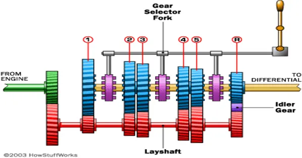
A manual transmission requires the driver to operate the gear stick and clutch in order to change gears, where one (typically the clutch) or both of these functions are automated. Most manual transmission for cars allows the driver to select any gear ratio at any time, for example shifting gears from 2nd to 4th or 5th to 3rd.
Procedure to construct the control logic
- On the Simulink interface, create an ‘chart’ block to define the stateflow as per given conditions.
- Inside the chart block, add junction block to terminate the signal flow and to return the null value.
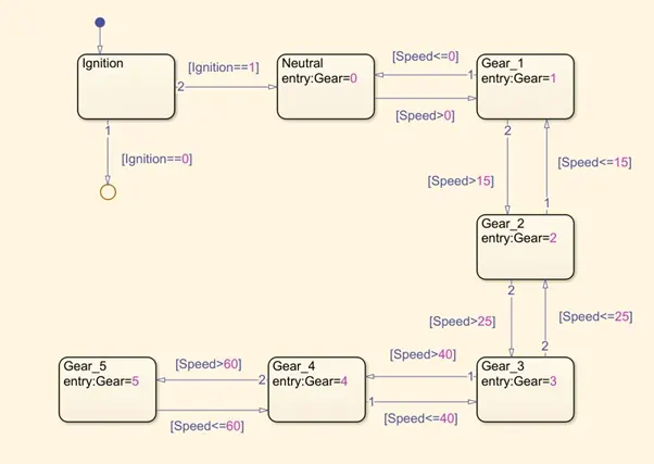
- When the ignition is OFF, value (0) the process is terminated at the junction else 1 is carried forward.
- When the speed is less than or equal to ‘0’ the process is terminated and gear ‘0’ is activated at the junction else ‘1’ is carried forward.
- When the speed is greater than ‘0’ and less than or equal to ‘15’, the process is terminated and the gear ‘1’ is activated.
- When the speed is greater than ‘15’ and less than or equal to ‘25’, the process is terminated and the gear ‘2’ is activated.
- When the speed is greater than ‘25’ and less than or equal to ‘40’, the process is terminated and the gear ‘3’ is activated.
- When the speed is greater than ‘40’ and less than or equal to ‘60’, the process is terminated and the gear ‘4’ is activated.
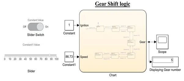
- When the speed is greater than ‘60’ the process is terminated and the gear ‘5’ is activated.
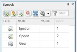
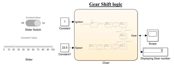
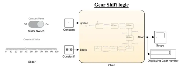
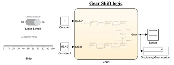
- In this stateflow chart, we have to give the ignition and speed as input symbols and gear as output symbol.
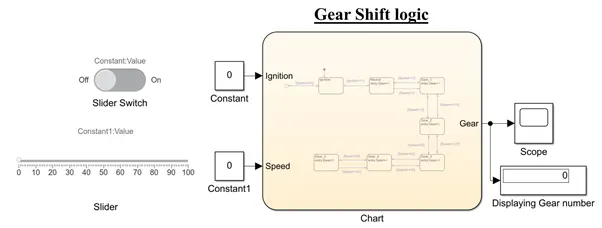
- Two separate constant blocks are connected to ignition and speed as inputs. These constant blocks are connected to sliding switches to ON/OFF the ignition supply and slider to indicate the speed. When the value is ‘0’ the sliding switch if ‘OFF’ and when the value is ‘1’ the sliding switch if ‘ON’.
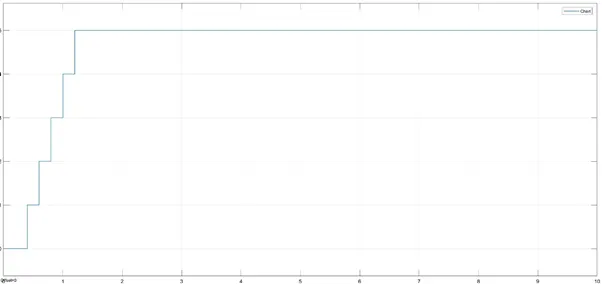
- The output (Gear) from the chart block is connected to a common scope block to obtain the final results and gives the final plots. Added one display block to show the gear number.
Stateflow
Symbols
Ignition – OFF
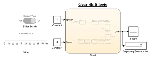
Ignition – ON; Speed – 0; Gear - 0
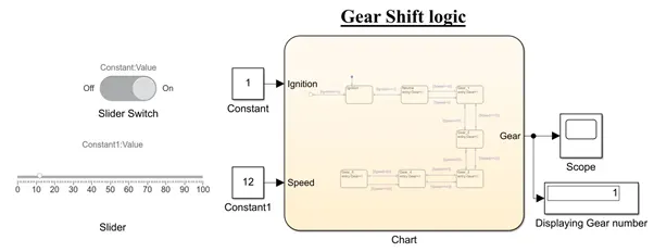
Ignition – ON; Speed – 0-15; Gear - 1
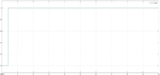
Ignition – ON; Speed – 16-25; Gear – 2
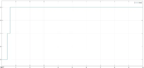
Ignition – ON; Speed – 26-40; Gear – 3
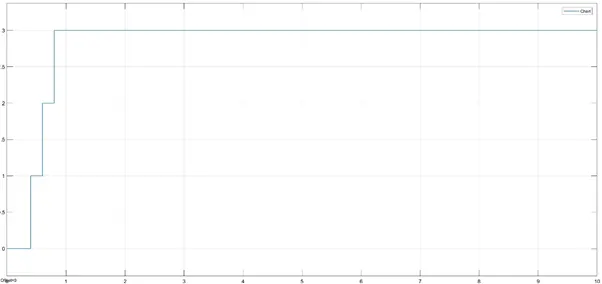
Ignition – ON; Speed – 40-60; Gear – 4
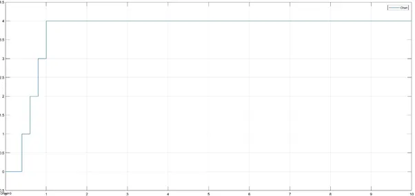
Ignition – ON; Speed – Above 60; Gear – 5
CONCLUSION:
Hence, we have created a control logic by creating stateflow chart of ‘Washing Machine’ and ‘Gear shifter’ according to the given conditions.
REFERENCES:
https://in.mathworks.com/products/stateflow.html
https://in.mathworks.com/discovery/control-logic.html
https://en.wikipedia.org/wiki/Transmission_(mechanics)