Control Logic of Washing Machine and Gear Shift Logic Implementation using Stateflow
OBJECTIVE:
- To Implement control logic of a “washing machine” using Stateflow as per given sequence:
- If the power supply is available, the system gets activated.
- If the Water supply is not available, stop the process & indicate through L.E.D.
- Soaking time should be 200s followed by washing time of 100 seconds.
- Then rinsing happens for next 20 seconds & dryer runs for 50 seconds.
- After all the processes have completed, turn on the ‘Finished L.E.D.’.
- To make a Simulink chart for the “Gear Shift” Logic using Stateflow as per below conditions:
|
Speed Range (in km/hr.) |
Gear Number |
|
0 to 15 |
1 |
|
16 to 25 |
2 |
|
26 to 40 |
3 |
|
41 to 60 |
4 |
|
Above 61 |
5 |
Give Speed input while Simulation is running and display the Gear Number.
SOFTWARE USED:
- StateFlow: StateFlow is a control logic tool developed by Mathworks which provides a Graphical Language that includes state transition diagrams, flow charts, state transition tables, and truth tables. Stateflow can be used to describe how MATLAB® algorithms and Simulink® models react to input signals, events, and time-based conditions. Stateflow enables you to design and develop supervisory control, task scheduling, fault management, communication protocols, user interfaces, and hybrid systems.
Using Stateflow, we can model combinatorial and sequential decision logic that can be simulated as a block within a Simulink model or executed as an object in MATLAB. Graphical animation enables you to analyze and debug your logic while it is executing. Edit-time and run-time checks ensure design consistency and completeness before implementation.
SOLUTIONS:
Solution to Objective 1:
Theory:
A washing machine is a home appliance that is used to wash laundry. This appliance uses water and laundry detergent (in solid or liquid form) to wash the laundry. The processes generally involved in washing machines are:
- Prewashing: The option called prewash indicates filling the drum with a certain water level and mixing it up with the detergent powder. All this option helps to wash out all the stains including the stubborn dirt very well from the clothes. This is possible as we soak the whole clothes placed into the drum. Finally, the water is drained. In my Simulink model, this process is a reflection of the state named ‘Soak’.
- Washing: At this particular time, the machine uses agitation which is for mixing both water and detergent, which in turn moves the clothes all around the drum.
- Rinsing: The option called rinsing is known for being a multi-task option. During this particular cycle, the soapy water is taken from the clothes. And all the fresh or pure water is sparkled to the clothing available in the tub. This particular rinse option holds responsible for taking soapy water out of the washer without facing any kind of difficulties. Finally, the agitation with plain water is considered the last step in the rinsing option.
- Spinning: Spinning is done to dry the entire clothes before getting to the end of the actual wash cycle. The speed of one particular spin is calculated in revolutions per minute (rpm). More the speed of spin, more the amount of water extracted from clothes and easier it becomes to dry the clothes. In my model, this process is a reflection of the ‘Drying Process’.
My Simulink Model along with the StateFlow Chart:
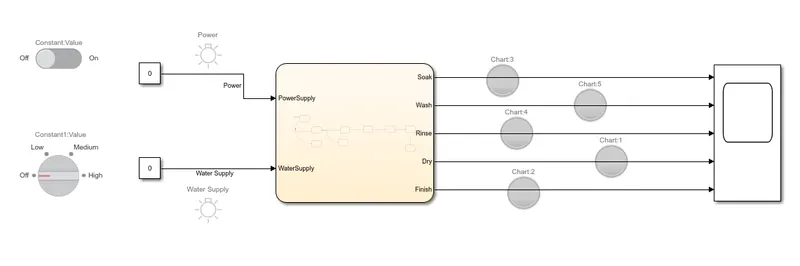
My Simulink Model for implementing control logic of Washing Machine
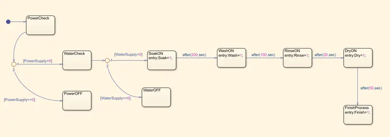
Control Logic of Washing Machine implemented using Stateflow with the help of ‘Chart’ Block
Steps undertaken for completing this objective:
- Open a Blank Simulink Model Page.
- Add a ‘Chart Block’ to the page and double-click on it to implement the control logic for the Washing machine.
- Inside the Chart block, the first state indicates that the process after it will check whether the Power supply is on or off. If the power supply is on i.e. ‘1’, the process will move on to further stages of washing. If the power supply is detected to be off, the process terminates to a state where the value returned is ‘0’.
- If the power supply is detected to be ‘On’, then the process moves on to a state where the system will check whether the Water Supply is on or off. If the water supply is on i.e. ‘1’, the process will move on to further stages of washing. If the water supply is detected to be off, the process terminates to a state where the value returned is ‘0’.
- After the water supply has been detected to be ‘On’, then the process moves on to the ‘SoakON’ block which basically indicates the system to activate the Soaking Process (corresponds to Prewashing Process).
- After the Soaking Process, the ‘WashON’ block gets activated (directs the system to activate the Washing Process) but only after the ‘SoakON’ block has remained active for 200 seconds.
- After the Washing Process, the ‘RinseON’ block gets activated (directs the system to activate the Rinsing Process) but only after the ‘WashON’ block has remained active for 100 seconds.
- After the Rinsing Process, the ‘DryON’ block gets activated (directs the system to activate the Drying Process) but only after the ‘RinseON’ block has remained active for 20 seconds. The Drying Process corresponds to the spinning process in the washing machine.
- After the ‘DryON’ block has remained active for 50 seconds, the process then terminates to the ‘FinishProcess’ state which signals to the system that the process is done.
- The ‘PowerSupply’ and ‘WaterSupply’ has been defined as input data to the chart block and ‘Soak’, ‘Wash’, ’Rinse’, ’Dry’ and ‘Finish’ has been defined as output data from the ‘Chart’ block.
- The input ports of the ‘Chart’ Block named ‘WaterSupply’ and ‘PowerSupply’ are connected to the constant blocks. These constant blocks are connected to input switches. The ‘constant’ block connected to the ‘PowerSupply’ port is connected to a ‘Slider Switch’ block and the ‘constant’ block connected to the ‘WaterSupply’ port is connected to the ‘Rotary Switch’ Block.
- ‘Lighting Switch’ Blocks are connected to the Simulink signals connecting the input ports and the constant blocks. This Lamp Blocks will indicate whether the switches are in ON or OFF position.
- A Scope Block is added to the Model page and all the output ports of the ‘Chart’ Block are connected to this ‘Scope’ block.
- All the output ports are connected to the ‘Lamp’ Blocks where the lamp will be red if a particular output process is not complete or not activated and will be of ‘red’ color if the corresponding output process is complete.
Observations/Results:
- Power: OFF ; Water Supply: OFF ; Time: 0 seconds.
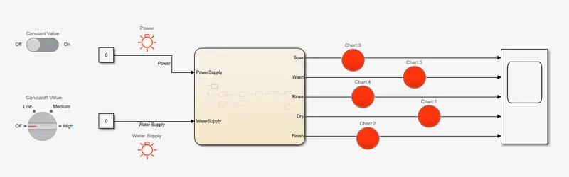
- Power: OFF ; Water Supply: OFF ; Time: 200 seconds.
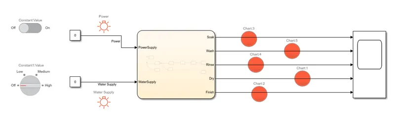
- Power: OFF ; Water Supply: OFF ; Time: 400 seconds.
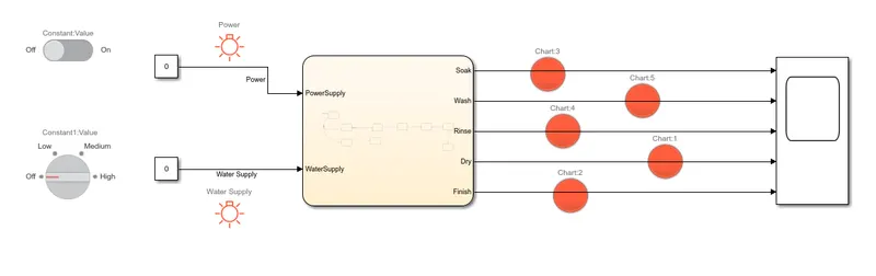
- Power: ON ; Water Supply: OFF ; Time: 0 seconds.
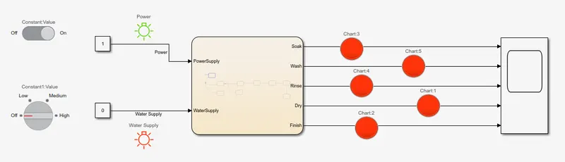
- Power: ON ; Water Supply: OFF ; Time: 200 seconds.
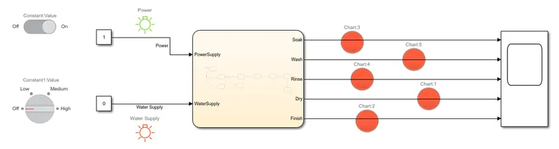
- Power: ON ; Water Supply: OFF ; Time: 400 seconds.
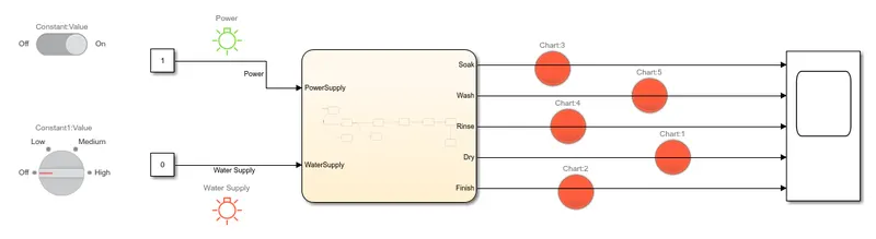
- Power: ON ; Water Supply: ON ; Time: 0 seconds.
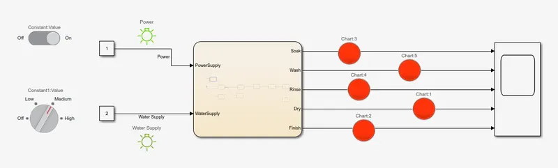
- Power: ON ; Water Supply: ON ; Time: 16 seconds.
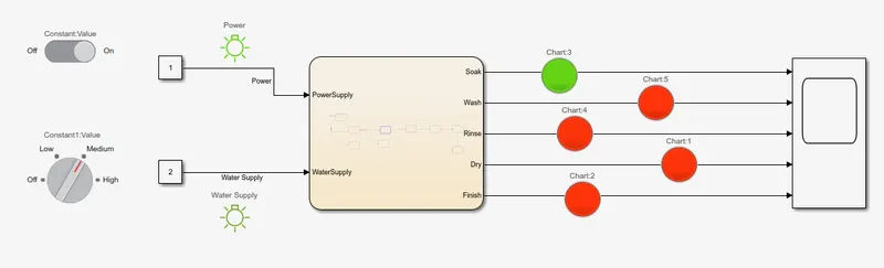
- Power: ON ; Water Supply: ON ; Time: 216 seconds.
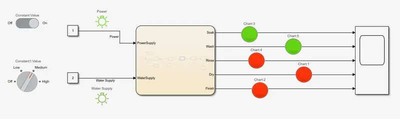
- Power: ON ; Water Supply: ON ; Time: 320 seconds.
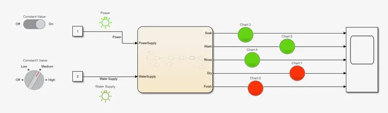
- Power: ON ; Water Supply: ON ; Time: 344 seconds.
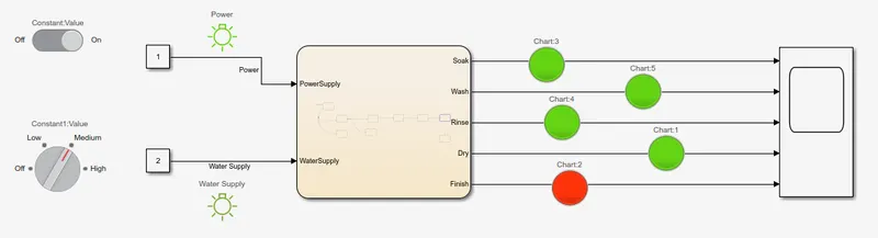
- Power: ON ; Water Supply: ON ; Time: 400 seconds.
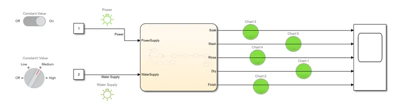
Solution to Objective 2:
Theory:
The gearbox is a mechanical device which is used to increase the output torque or to change the speed (RPM) of a motor. The shaft of the motor is connected to one end of the gearbox and through the internal configuration of gears of a gearbox, provides a given output torque and speed determined by the gear ratio.
To maintain engine speed on all conditions of load and vehicle speed, the gearbox uses a system to maintain engine speed, while sacrificing the same road speed. To enable the engine to run faster on-road wheels as well as to multiply the torque, a gearbox is required.
My Simulink Model along with the StateFlow Chart:
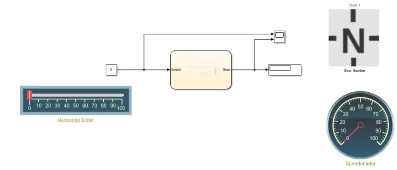
My Simulink Model for implementing Gear Shift logic of Gearbox
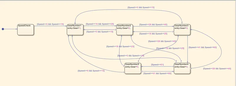
Gear Shift Logic of Gearbox implemented using Stateflow with the help of ‘Chart’ Block
Steps undertaken for completing this objective:
- Open a blank Simulink Model page.
- Add a chart block to the page and double click on the ‘Chart’ block to implement the ‘Gear-Shift’ logic of a gearbox.
- Inside the Chart block, the first state indicates that the process after it will check the speed of the vehicle. If the speed of the vehicle is greater than equal to 0 kmph and lesser than equal to 15 kmph then the next state gets activated i.e. Gear 1 gets activated.
- When Gear 1 stays activated and then the vehicle speed rises, if the vehicle speed is now greater than or equal to 16 kmph and lesser than or equal to 25 kmph, then the next state gets activated i.e. Gear 2 gets activated.
- When Gear 2 stays activated and then the vehicle speed rises, if the vehicle speed is now greater than or equal to 26 kmph and lesser than or equal to 40 kmph, then the next state gets activated i.e. Gear 3 gets activated.
- When Gear 3 stays activated and then the vehicle speed rises, if the vehicle speed is now greater than or equal to 40 kmph and lesser than or equal to 60 kmph, then the next state gets activated i.e. Gear 4 gets activated.
- When Gear 4 stays activated and then the vehicle speed rises, if the vehicle speed is now greater than or equal to 61 kmph , then the next state gets activated i.e. Gear 5 gets activated.
- All the Gear Activation states are interconnected to each other on the basis of Vehicle Speed reduction. For example, if the speed of the vehicle is currently 55 kmph i.e. Gear 4 is active and due to some reason, the vehicle, on braking, had to reduce it’s speed to 17 kmph, then Gear 4 gets disconnected and Gear 2 gets activated.
- For vehicle speed increase, since the speed increase is gradual, and since all the corresponding gears for speed ranges need to get activated, therefore a Gear Activation state is only connected to it’s next higher speed range’s Gear Activation state. For example, if I want to increase my speed from 5 kmph(Gear 1) to 75 kmph(Gear 5), Gear 5 cannot be activated directly from Gear 1. All the Gear States between Gear 5 and Gear 1 need to gets activated in ascending order in order to go from Gear 1 to Gear 5. (Gear1 -> Gear 2 -> Gear 3 -> Gear 4 -> Gear 5).
- The ‘Speed’ is defined as input data for the Stateflow chart and ‘Gear’ is output data for the Stateflow chart.
- The input port of the Chart block (corresponds to Speed) is connected to a ‘Constant’ block via a Simulink Signal.
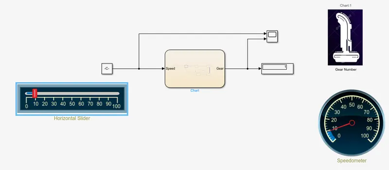
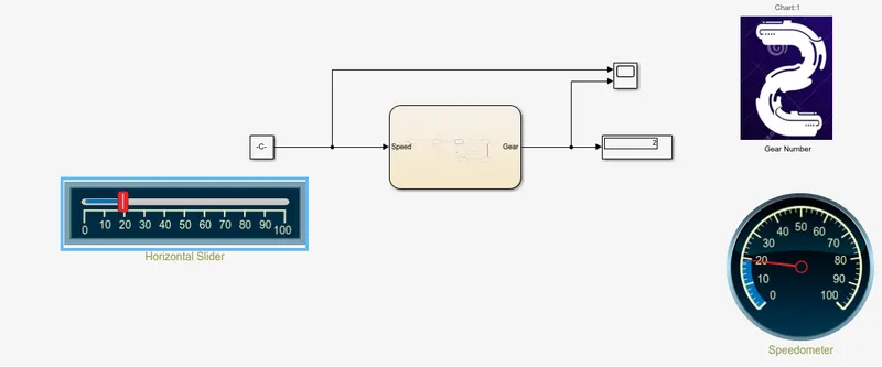
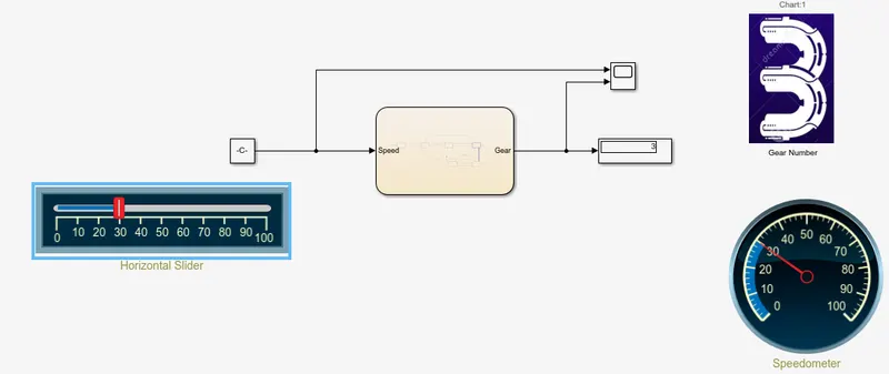
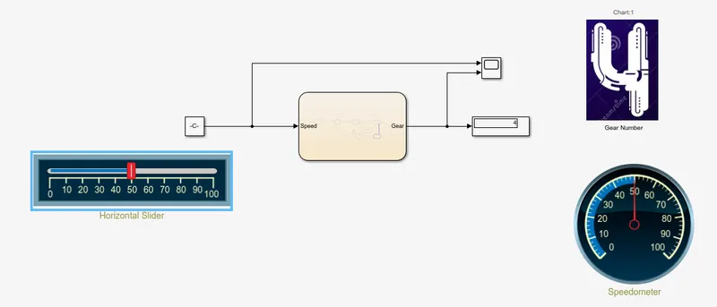
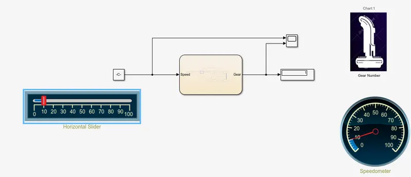
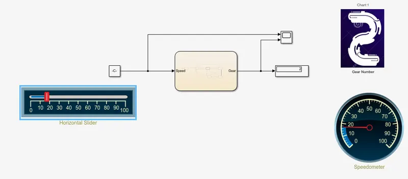
- A ‘Horizontal Silder’ block is connected to this ‘Constant’ block. The ‘Horizontal slider’ block will be used to adjust and vary the speed being fed to the ‘Chart’ Block.
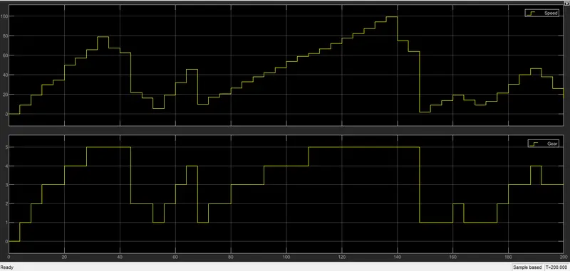
- A Scope Block is added to the page and is connected to the Output port of the ‘Chart’ Block (corresponds to Gear). The Simulink Signal being fed from the Constant block to the input port of the ‘Chart’ Block is branched out midway and connected to the Scope Block so that Gear Numbers can be observed for their corresponding input speed.
- A ‘Circular Gauge’ block is added to the page and connected to the Simulink Signal being fed from the ‘Constant’ block to the Input (Speed) port of the ‘Constant’ block. This ‘Circular Gauge’ corresponds to the Speedometer of the vehicle and whatever variations/adjustments are made to the speed using the ‘Horizontal Slider’ block, the changes will be reflected in the ‘Circular Gauge’ Block.
- A ‘MultiStateImage’ block has also been used in my model. This block displays the Gear number in the form of Custom images. This block has been connected to the Simulink Signal connecting the Scope Block and the output port (corresponds to Gear) of the ‘Chart’ block.
- Additionally, a ‘Display’ block has also been connected to the output port (corresponds to Gear) of the ‘Chart’ Block where values returned by the variable ‘Gear’ will be displayed.
Observations/Results:
- Speed Range: 0-15 ; Gear: 1
- Speed Range: 16-25 ; Gear: 2
- Speed Range: 26-40 ; Gear: 3
- Speed Range: 41-60 ; Gear: 4
- Speed Range: Above 60 ; Gear: 5
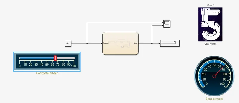
- Speed Range: 16-25 ; Gear: 2
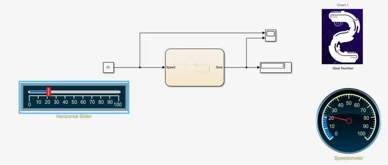
- Speed Range: 26-40 ; Gear: 3
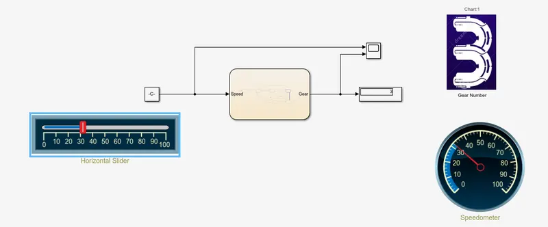
- Speed Range: 41-60 ; Gear: 4
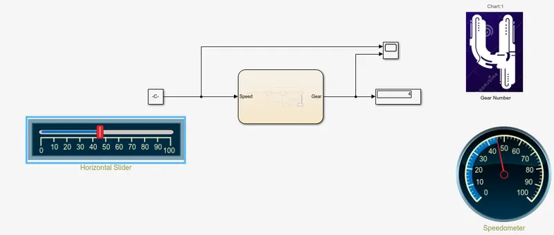
- Speed Range: 0-15 ; Gear: 1
- Speed Range: 16-25 ; Gear: 2
- Gear and Speed Plot for various inputs of Speed given during the Simulation:
CONCLUSION:
- The Control Logic of Washing Machine and Gearbox was implemented using StateFlow and the models were designed using Simulink as per the conditions mentioned and the behaviour/output of the models were observed at various time intervals on simulation.