Week - 4
1.Control logic of washimg machine:
The control logic of the washing machine is explained using the below model,

The above stateflow model is used to implement the logic behind the washing machine.It takes two input x and y when the input is greater than 1 the state model starts to execute and when the input is less than 0 the model will stop working.
After the high input ,the model will go through the next step of washing for 200s.After that it will execute rinsing for 20s and the drying for 50 s.
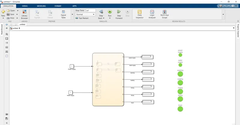
The above is the complete model for the execution of washing machine.The input is given from the constant block as1 so the input remains high for all the time.
The output is displayed in the display block and also the output is given to lamp for visual interfacing.The lamp block is used to route the signals without manual connection.When the signal is high the lamp will glow in green color and when the signal is 0 then the lamp will glow in red color.
2.Gear shift in simulink chart:
The gear shift logic of the vechicle is executed using the below model,
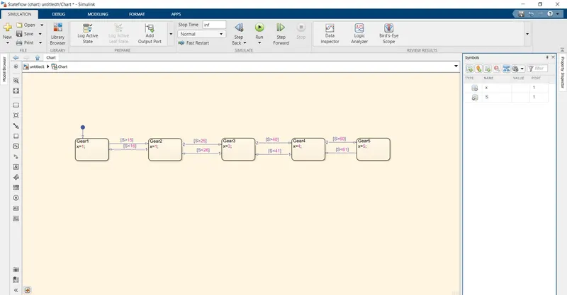
The above state flow model takes only the speed of the vechicle as input and compares the speed with threshold value given in the question and assign the gear value accordingly.
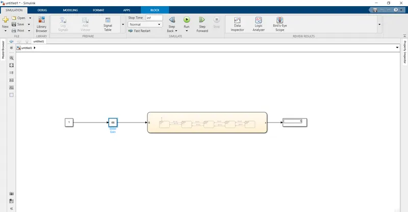
The speed input is given from a slider gain as it is used to change the value during the runtime of the model.The speed is compared at each state level and the corresponding gear value is found and it is displayed in the display block.