Week - 4
- Implement control logic of a “washing machine” using Stateflow as per given sequence:
- If the power supply is available, the system gets activated
- If the Water supply is not available, stop the process & indicate through LED
- Soaking time should be 200s followed by Washing time of 100s.
- Then rinsing happens for next 20s & dryer runs for 50s
After all the processes have completed turn on the finished LED
Solution:
The washing machine is operated in different stages.
Logic:
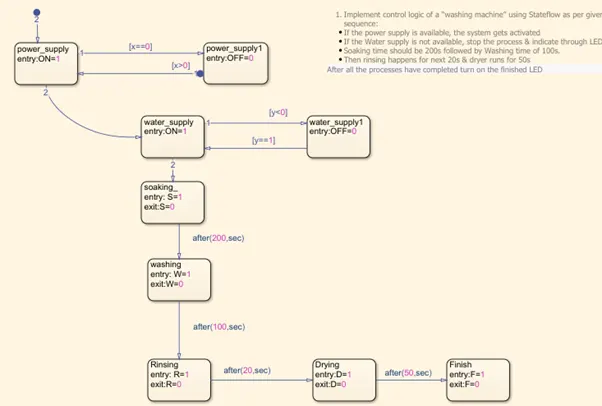
The machine works when the Power supply is on. And Starts operating only when the water supply is on.
Stages of working involve Soaking, Washing, Rinsing, and Drying. Each contribution is 200 seconds, 100 Seconds, 20 seconds, and 50 seconds. Then the work is finished.
The state flow is created when the work is finished.
Steps to create state flow
- Type chart in the workspace. It creates a state flow chart in Simulink.
- Select the Modelling tab and select the Selection pane.
- The type of variables is defined with input data, Output, or others.
Below the figure is the state flow logic chart.
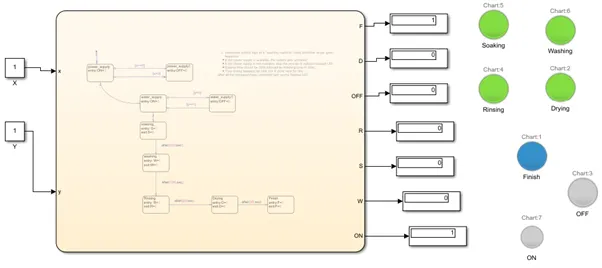
Input data and Output data are given with the input through Constant block and Output data are indicated with Lamp symbol.
The lamp is connected with the Display.
The simulation run time is given at 400 seconds. When the simulation is run, it works in a sequence and finally, after completion of the simulation, Finish LED shows a Blue color which says that the process of washing is completed.
2. Make a Simulink chart for the “Gear shift” logic as per below conditions:
Speed Range(kmph) Gear
0 to 15 1
16 to 25 2
26 to 40 3
41 to 60 4
Above 61 5
Give speed input while the simulation is running & display the gear number.
Solution:
The gear shift is the operation required whenever there is a change in speed.
So for different speeds, a change in gear is required. As per the gear numbers given for different speed ranges, the change is gear has opted.
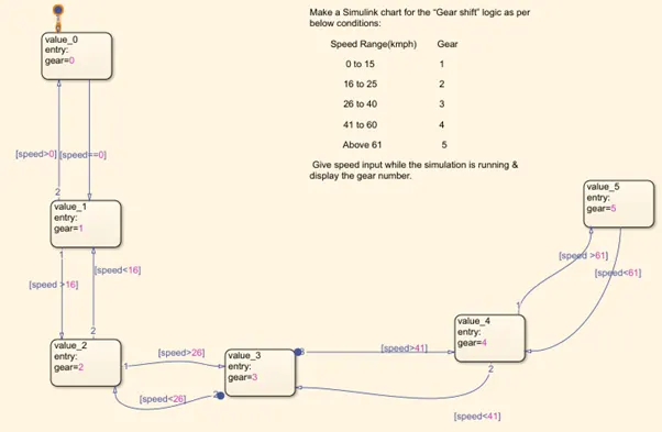
State entry input is speed and output is gear number.
In this state diagram, logic is as shown below.
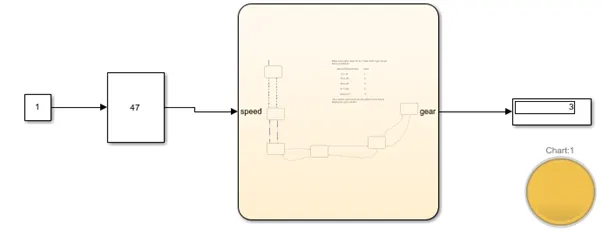
The constant block is given with input and is connected with the slider gain block. Slider gain block can be varied in its value during the run time of the program.
When the value is range differs accordingly, the gear number changes in display, and the same is reflected in lamp color.