Week - 4
Aim
To implement control logic of a washing machine using Stateflow and to make a Simulink chart for the Gear shift logic.
Objectives
1. To Create a simulink model for washing machine using state flow as per given conditions.
2. To Create a simulink model for gear shifting transmission at various speed range.
simulink model for washing machine using state flow as per given conditions.
Introduction
Washing Machine
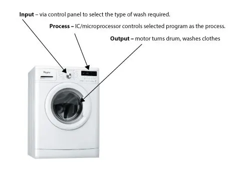
Its a machine which helps to wash our clothes with the various function like washing, rinsing, soaking spinning and drying our clothes within a given period of time. The centrifugal force between the clothes and the inside of the drum pushes them around in a circle. This force pushed the water from the clothes straight through the drum holes. The clothes experience the centrifugal force, and the water doesn't. Hence separates the solid or liquid dust from the clothes.
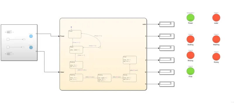
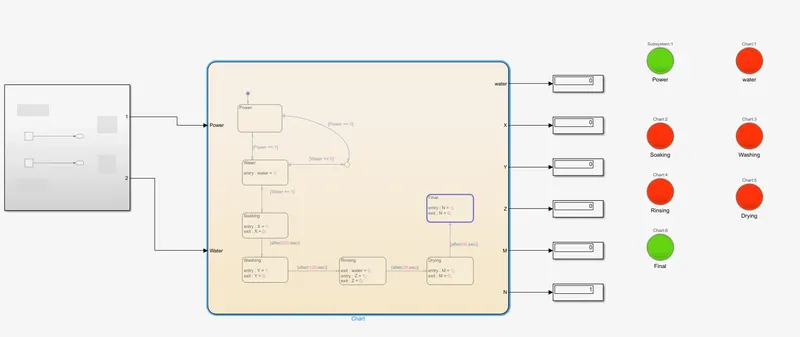
Model (simulink) for process of washing machine
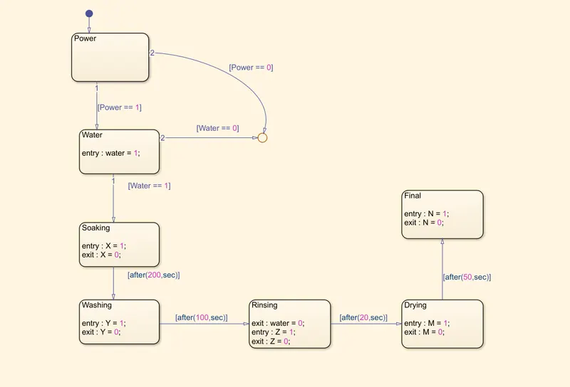
Various stages in washing machine as per given data :
i. Soaking for 200sec
ii. Washing for 100sec
iii. Rinsing for 20 sec
iv. Drying for 40sec
v. Final state
Expalnation :
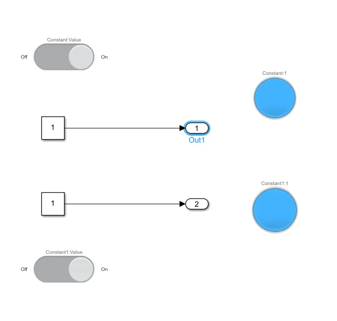
1. The constant block is used to define the power and water supply weather it need to be ON or OFF
2. The Slider switch block is used to indicate the condition of power and water supply with the help of lamp block for clear indication.
3. If the constant values of power and water supply are 1 then the input will be provided to state flow model, If not the process won't start.
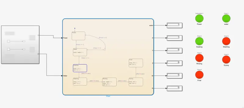
4. Once the power and the water supply are active the soaking process will start and it will took 200sec to complete.
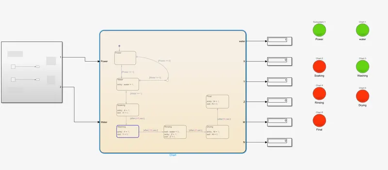
5. After the completion of soaking process the washing process will start and it will last for 100sec.
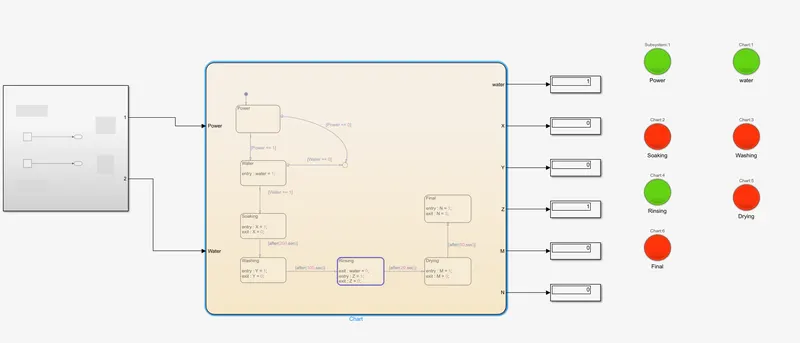
6. Then the rinsing process will continue foe another 20sec.
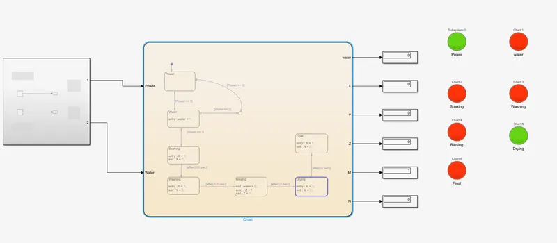
7. The drying process will takes place next for 50sec and finally after 370sec the entire process will cutoff and reaches the final state.
8. Each and every active process were indicated by a lamp block which are connected to display block.
Various stages in washing machine
1. Soaking process
2. Washing process
3. Rinsing Process
4. Drying Process
5. Final Process
Conclusion
Hence all the process in the washing machine are done according to the given data and the final led lamp was turned on.
simulink model for gear shifting transmission at various speed range
Introduction
Gear shift
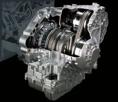
A transmission is a machine in a power transmission system, which provides controlled application of power. Often the term 5-speed transmission refers simply to the gearbox, that uses gears and gear to provide speed and torque conversions from a rotating power source to another device. The most common use is in motor vehicles, where the transmission adapts the output of the IC engine to the drive wheels. Such engines need to operate at a relatively high rotational spee, which is inappropriate for starting, stopping, and slower travel. The transmission reduces the higher engine speed to the slower wheel speed, increasing torque in the process. Transmissions are also used on bicycles, fixed machines, and where different rotational speeds and torques are adapted.
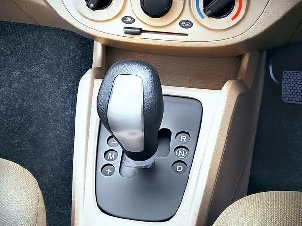
Often, a transmission has multiple gear ratios (or simply "gears") with the ability to switch between them as the speed varies. This switching may be done manually (by the operator) or automatically (by a control unit). Directional (forward and reverse) control may also be provided. Single-ratio transmissions also exist, which simply change the speed and torque (and sometimes direction) of motor output. In motor vehicles, the transmission generally is connected to the engine crank shaft via a flywheel or clutch or fluid coupling, partly because IC enginescannot run below a particular speed. The output of the transmission is transmitted via the drive shaft to one or more differentials, which drive the wheels. While a differential may also provide gear reduction, its primary purpose is to permit the wheels at either end of an axle to rotate at different speeds (essential to avoid wheel slippage on turns) as it changes the direction of rotation.
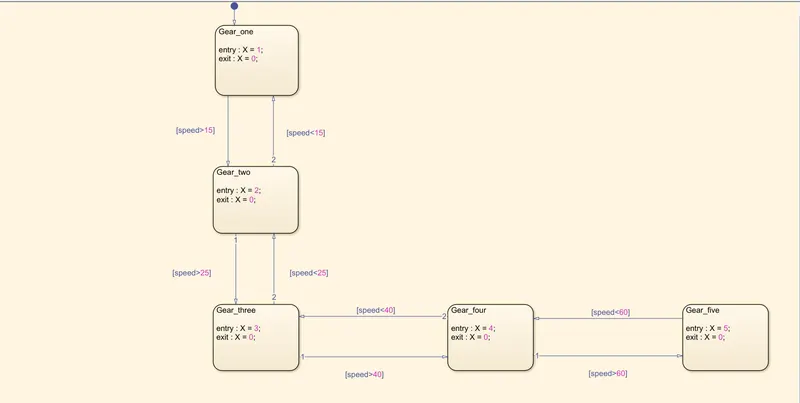
Operation of Gears according to their speed as given
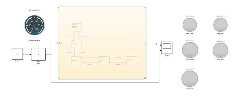
i. First gear - (0-15Kmph)
ii. Second gear - (16-25Kmph)
iii. Third gear - (25-40Kmph)
iv. Fourth gear - (40-60Kmph)
v. Fifth gear - (Greater than 60Kmph)
Model (simulink) Gear shifting
Explanation
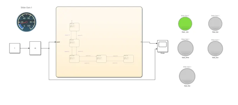
1. The Slider gain block helps to initiate various input speeds to the Transmission system to work.
2. At first the slider in teh slider gain block should be set at value 0
3. Once we increase the slider value the gear will automatically change according to the various speed provided in the state flow chart.
4. The first gear will active when the speed range is (0-15Kmph).
5. The second gear will active when the speed range is (15-25Kmph).
6. The third gear will active when the speed range is (25-40Kmph).
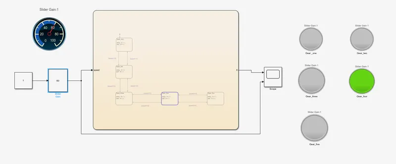
7. The fourth gear will active when the speed range is (40-60Kmph).
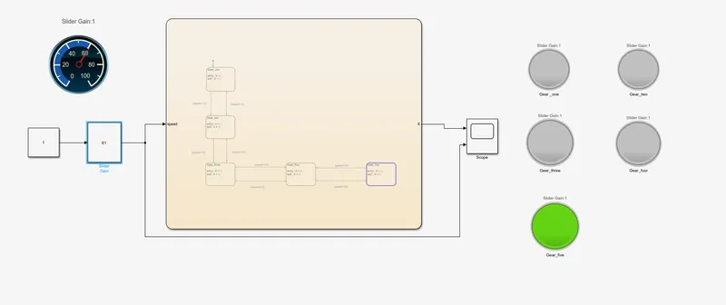
8. The fifth gear will active when the speed range is (greater than 60Kmph).
9. The variation of the speed can be visualized in the speedometer.
10. The speed can also reduced by reducing the gears.
Gear shifting at various speed levels
First Gear
The gear is active when the speed range is (0-15Kmph).
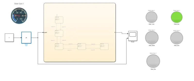
Second Gear
The gear is active when the speed range is (15-25Kmph).
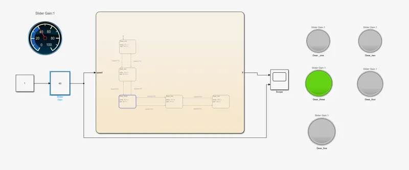
Third Gear
The gear is active when the speed range is (25-40Kmph).
Fourth Gear
The gear is active when the speed range is (40-60Kmph).
Fifth Gear
The gear is active when the speed range is (greater than 60Kmph).
Output Chart (Speed vs Gear shift)
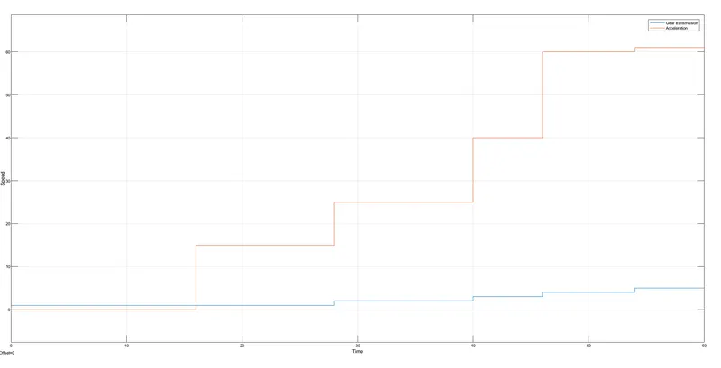
Hence the speed increases when the gear is shifting Up.
Conclusion
From the above diagram we can conclude that the speed input varies the gear shift according to the given values.