Week 4.2: Project - Transient simulation of flow over a throttle body
Aim:- To run Transient Simulation of flow over throttle body.
Objective:- Set up and run the transient simulation flow over throttle body.
Post process the results and show pressure and velocity contours.
Show the mesh (i.e surface with edges)
Show the plots for pressure, velocity, mass flow rate and total cell count.
Create an animation in which it throttle movement should be visible.
Throttle body:
The throttle body is an important part of your air intake system that controls the air flowing into your engine. It's located between your air intake and engine manifold where fresh air is pulled into the engine for the combustion process (which is located in carburetor).
Throttle body Application:
Automobile Engine
Internal Combustion Engine
Reciprocating Aircraft Engine
Steam Engine
Butterfly Valves:
Butterfly valves are quarter turn valves which employ center mounted circular flap that swing into and out of the flow stream.
Stagnation Pressure:-
It means the all properties of fluid is in steady state condition pressure, velocity and temperature is zero (initial).
Case Setup:-
- Application Type: Time based.
- Material:-Air, gas Simulation, reaction Mechanism (N2,O2).
Simulation Parameter:-
- Run parameter:- Transient flow, fully hydrodynamic and compressible.
- Steady-state Monitor:-
- Avg Velocity at Outlet
- Avg Pressure at outlet
- Mass Flow Rate at Outlet
- Simulation Time Parameter:-
- Start time = 0 sec
- End time = 0.01 sec
- Initial Time step = 1e-9 s
- Minimum time step = 1e-9 s
- Max time step = 1
- Max convection CFL limit = 1
- Boundary Condition:-
- Elbow Wall
- Boundary type = Wall
- Wall motion type = stationary
- surface movement = Fixed
- temperature at bounary condition = 300k
2. Inlet boundary Id_2
- Boundary type = Inlflow
- Inlet Pressure= 150000 Pa
- temperature at bounary condition = 300k
- Species Boundary Condition = Air (O2=23% & N2=77%)
3. Throttle Id_3
- Boundary type = Wall
- Wall motion type = Rotation
- surface movement = Moving
- temperature at bounary condition = Zero Normal gradient
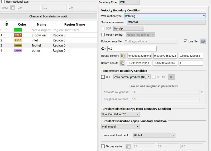
- Rotation file name = trottle_position.in
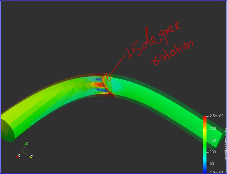
- Rotation angle at (0 sec = 0 degree & 0.02 sec = 25 degree).
4. Outflow boundary Id_4
- Boundary type = Outflow
- Inlet Pressure= 100000 Pa
- temperature at bounary condition = 300k
- Species Boundary Condition = Air (O2=23% & N2=77%).
Region and Initialization
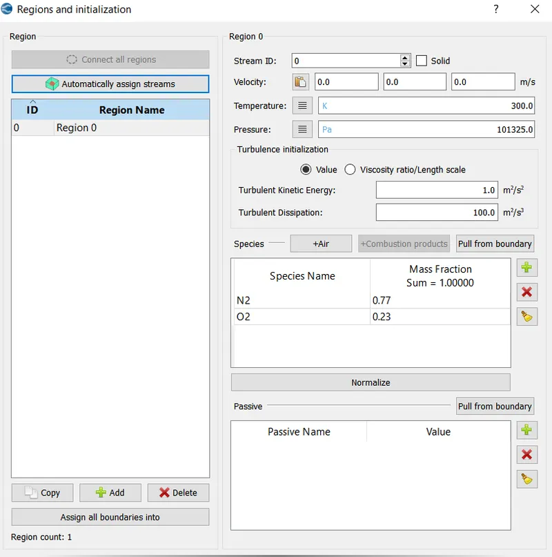
- Grid Controls:-
Base Grid Size (X=4e-3, Y=4e-3 & Z=e-3)
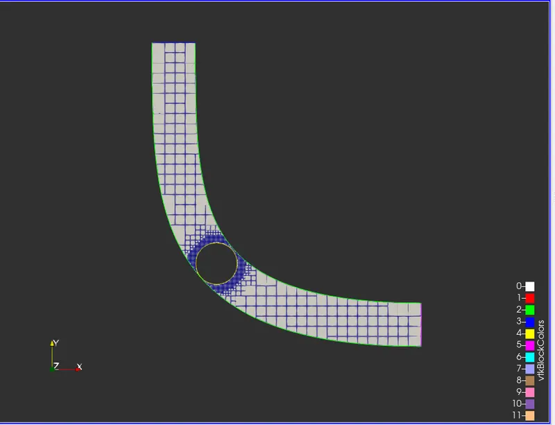
- Fixed Embedding
Entity Type = Boundary
Boundary ID = Throttel
Mode =Permanent
Scale = 2
Embed Layer = 4
- Converge Geometry
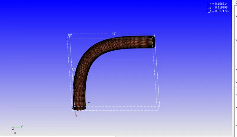
Meshing body
CFD used a cut cell cartetian method is that the body fitted to mesh. That means the body perfectly meshed with our geometry, reducing the number of inaccuracies that propagate the rest of domain.
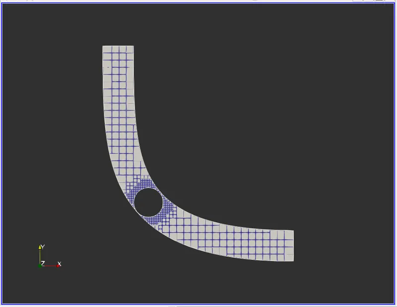
Paraview Geometry
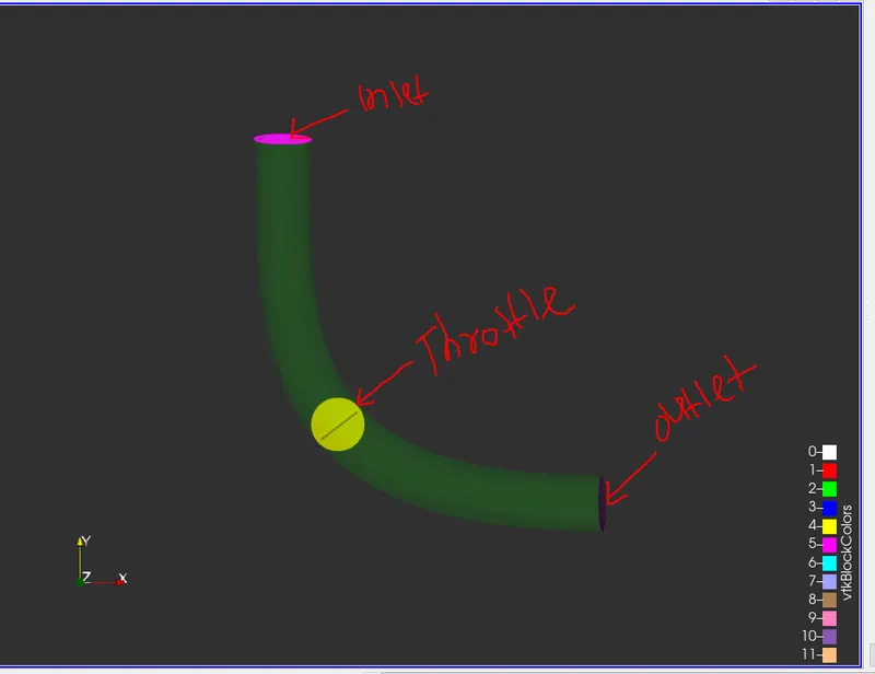
Throttle body at 0 degree roration.
Throttel body rotation at 25 degree.
Operations In Paraview
Fixed Embedding
Opacity
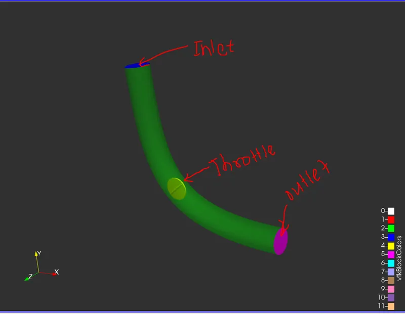
Glyph Vector in Velocity direction
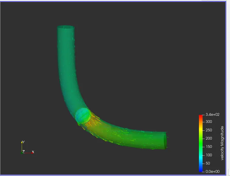
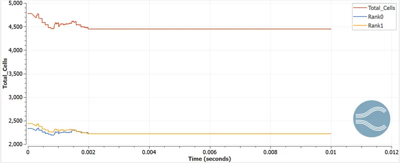
Result
Total Cells = 4900
Rank 0 = 2300
Rank 1 = 2450
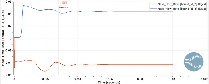
Mass Flow rate at Inlet/Outlet
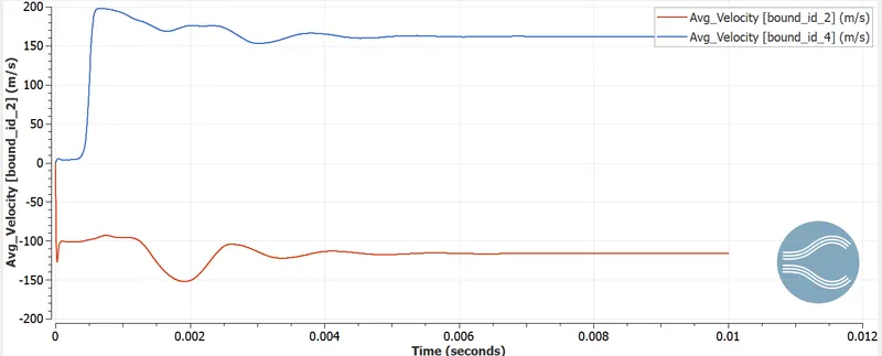
Avg Velocity at Inlet/Outlet
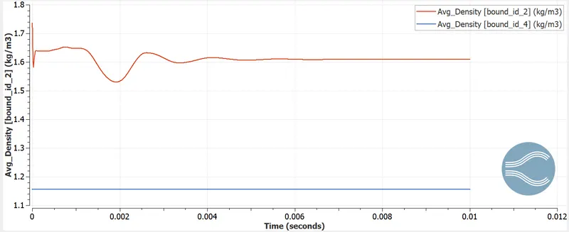
Avg Density inlet/Outlet
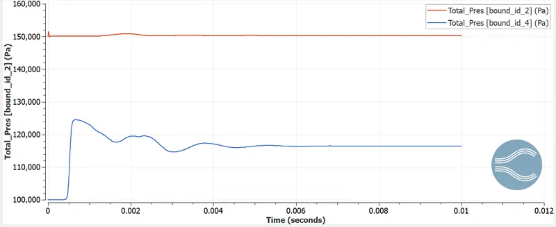
Total Press Inlet/outlet
Animation video
Conclusion
- The velocity graph shows the velocity decrease at throttle and then stabel at exit point.
- pressure increase at throttle and decrease and stabel at exit point.
- In transient flow the throttle body rotate around its cylindrical axis so the flow slightly closed pressure increase and velocity becomes slow down. It show in animation near throttle.
- Mostely the transient flow we used in the engine fuel injector near the carborater.
- We have increase the embedding size at the throttle body most flow becomes velocity decrease and pressure increase.