Week 4.2: Project - Transient simulation of flow over a throttle body
Aim: - To run a transient simulation for flow over throttle body.
Objective: -
1. To setup a case for transient simulation for flow over throttle body model in Converge CFD.
2. To rotate the valve in following configuration at given time –
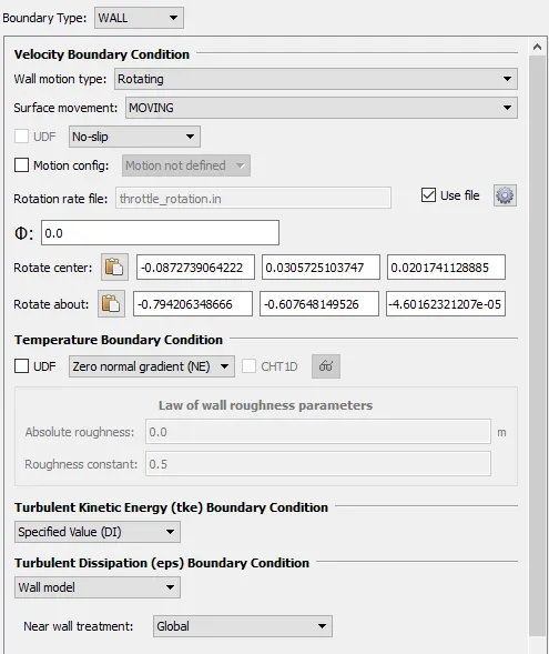
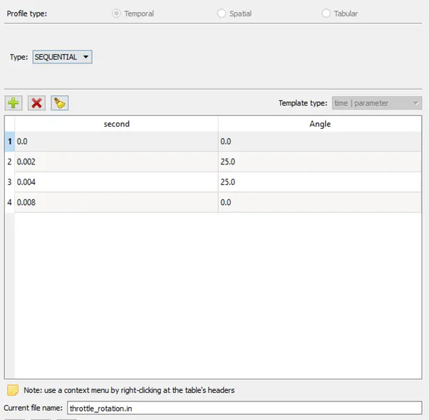
- 0 to 2 ms - rotate 25 degrees.
- 2 to 4 ms - idle at 25 degrees.
- 4 to 8 ms - rotate back to its original position.
3. To post process the result and plot velocity and pressure contours along with mass flow rate variations.
Introduction: -
Throttle – It is mechanism by which fluid flow is managed by constriction or obstruction. informally, it refers to any mechanism by which the power or speed of an engine is regulated, by increased or decreased by the restriction of inlet gases. The method of restriction is usually butterfly valve for internal combustion engines.
Throttle Body – It is the part of the air intake system that controls the amount of air flowing into the engine, in response to driver accelerator pedal input in the main.
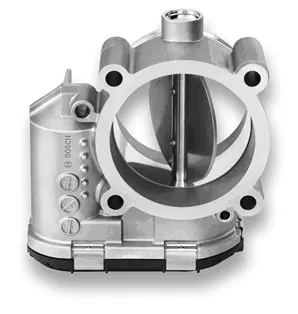
Throttle Body
End Time Calculation:
To guess a proper end time a steady state fully open simulation is done where average velocity at inlet is 16.14 m/s
For distance we take the longer side length, which is around l_y = 0.12 m.
time = distance/speed = 0.12/16.14 = 7.435e-3 sec = 7.43ms `~~` 10 ms
fluid completes it's travels roughly in 7.5 sec along the body. To give proper tolerance and get accurate result we will simulate for 10 milli sec.
Model view:
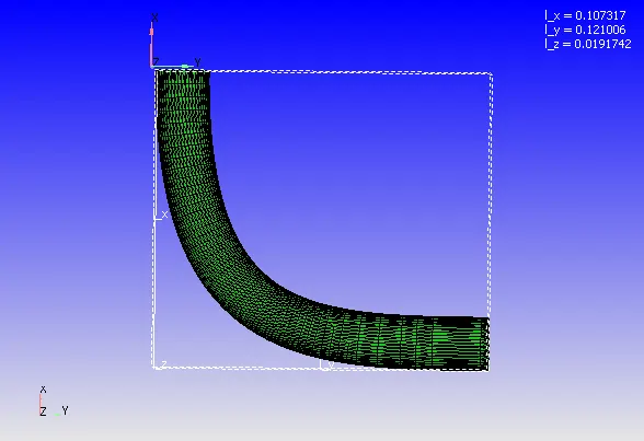
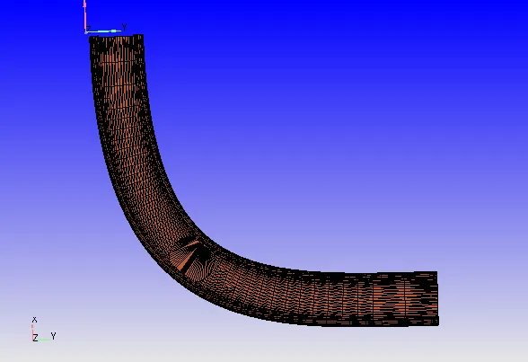
The model outer layer triangles are deleted which resembles thickness as no CHT (Conjugate Heat transfer) analysis is done and only fluid volume is used.
Case Setup: -
- Time Based application type.
- Gas simulation with Air as predefined mixture
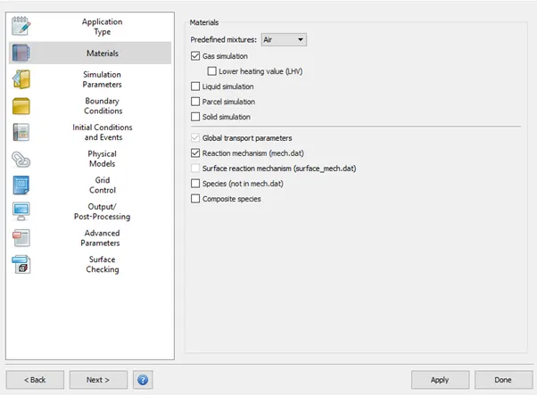
- Pressure Based Transient Solver is used with Compressible Gas Flow solver and PISO Navier-Stokes’s solver scheme.
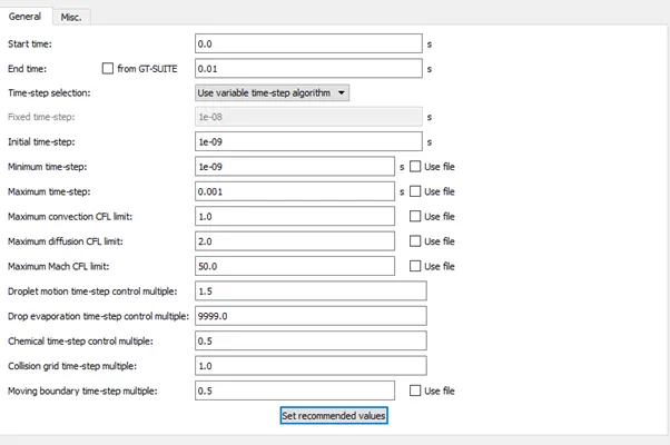
- The solution run for 10 ms with minimum time step of 1e-9 s and maximum up to 1 sec.
- Boundary Condition:
- Inlet - Type = Inflow, Pressure = 1.5e5 Pa, Species = O2:0.23, N2: 0.77
- Outlet - Type = outflow, Pressure = 1e5 Pa, Species = O2:0.23, N2: 0.77
- Elbow – Type = wall, No slip Condition
- Throttle - Type = wall, No slip Condition
- The throttle is set to rotate to get the given configurations –
- The throttle_rotation.in file is set as required rotation setting –
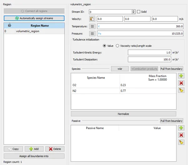
- Volumetric Region are initialized with mass fraction of O2: 0.23 and N2: 0.77. The boundaries are assigned their region type.
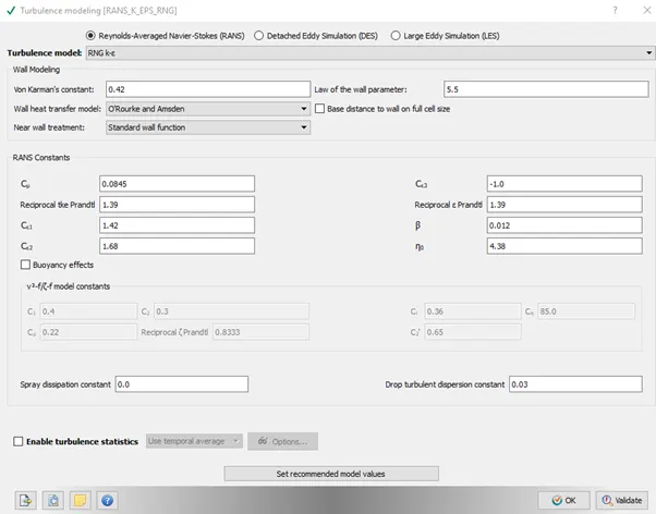
- RNG K-epsilon is used for turbulence modelling with recommended values.
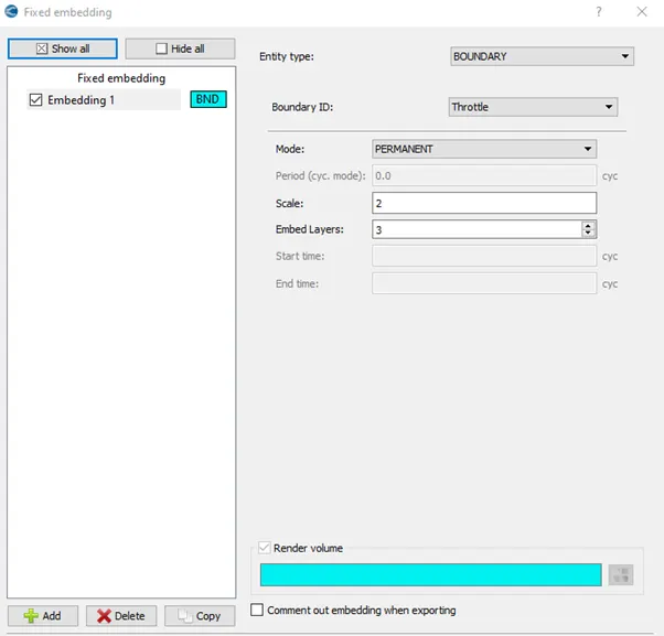
- Base grids of 2e-3 m are generated for all axis. Fixed embedding is also added to top and Bottom wall to get better results.
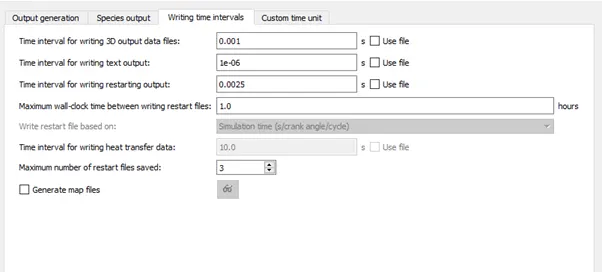
- 3D output data is written after every 1 ms –
- The input files are exported to a folder to further solving.
Solving using Cygwin:
An executable “mpiexec.exe” is placed with the exported folder. The Cygwin directory is navigated to the above saved folder and following code is entered to solve the problem.
"mpiexec.exe -n 2 "C:\Program Files\Convergent_Science\CONVERGE\3.0.16\bin\intelmpi\converge.exe" restricted </dev/null> logfile &"
where address in quotes gives the path of folder containing input file exported earlier.
Post-Processing:
Post-Processing is done with the help of Converge CFD post processing tab –
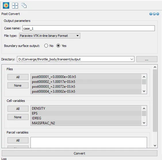
with these the output 3D data is converted in ‘.vtm’ file and contours and animations are prepared though ParaView.
Results: -
Base mesh at the start –
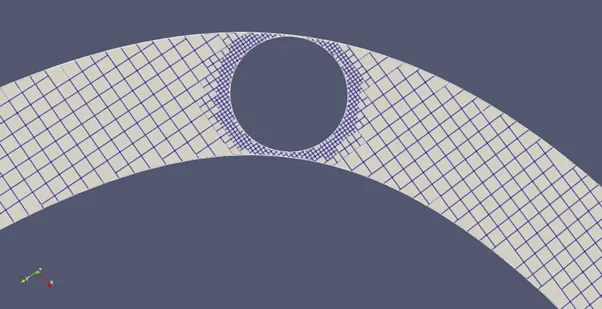
Since it involves a dynamic meshing to accommodate the rotation, therefore mesh changes with time. This dynamic meshing can be seen in following –
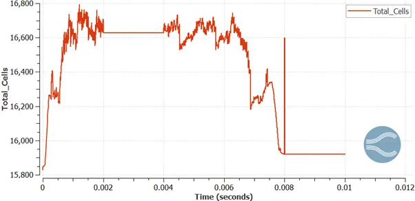
As the mesh changes total number of cells varies accordingly –
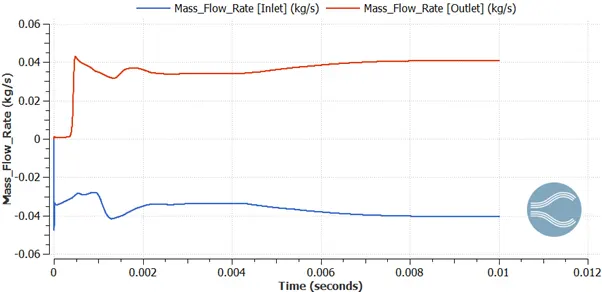
Mass-Flow-Rate:
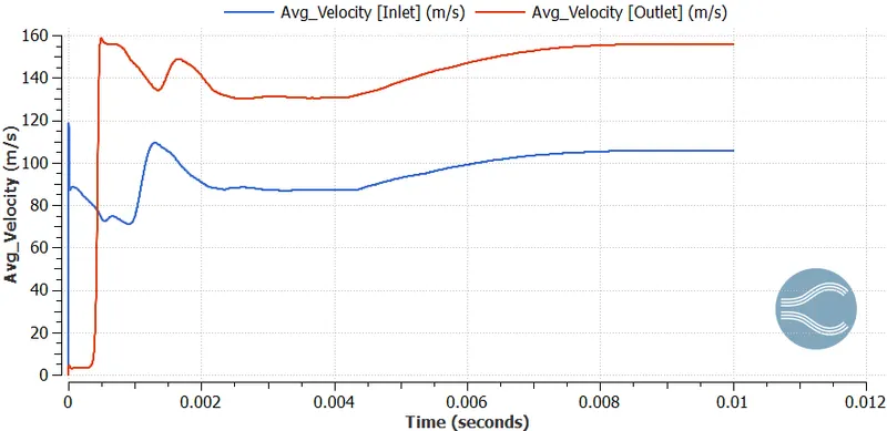
Average Velocity:
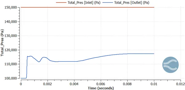
Pressure:
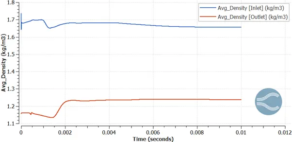
Average Density:
Velocity Animation:
Pressure Animation:
Velocity Animation on midplane:
Streamline animation around butterfly valve:
Conclusion:
- when the valves rotates 25 degree the mass-flow-rate decreases and when it returns to original position the flow increases as its fully opened.
- pressure at outlet decreases as valve rotates depressurising upstream.
- Mesh is generated at every mili seconds as rotation induces change, therefore number of cell varies at each time step.