Week 4.2: Project Transient simulation of flow over a throttle body
- Transient simulation of flow over a throttle body
- Aim - To perform transient simulation of flow over a throttle body
- Objective -Set up a transient-state simulation of flow across the throttle body during convergence.
- Export all input files and run the simulation in Cygwin.
- Contour representation of flow velocity and pressure in an elbow pipe.
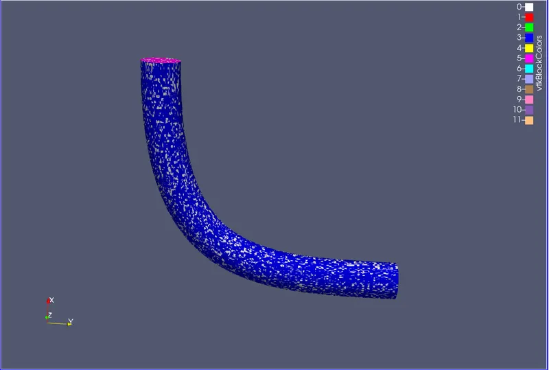
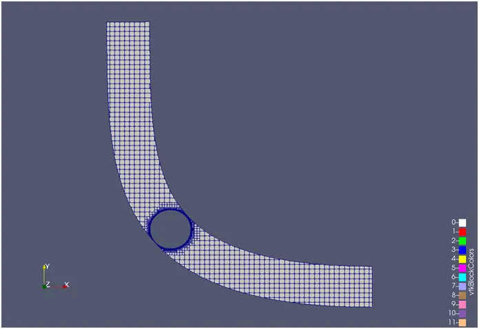
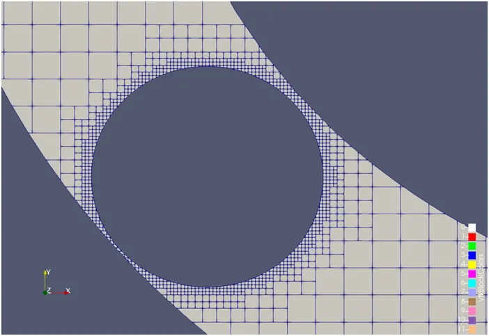
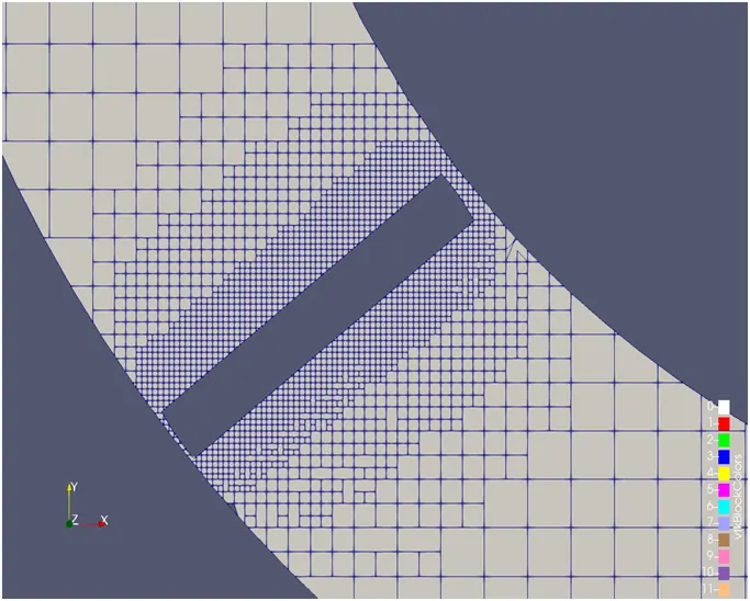
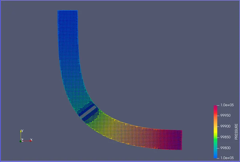
- Shows the mesh (that is, the surface with edges) by creating midplanes/cuts along the z direction.
- Convergence charts for velocity, pressure, mass flow rate, and total cell count.
- Describe the plot and write a detailed report on the project.
- Create an animation in Paraview to show the flow through the throttle during the initial stabilization phase.
- Introduction
-
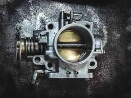
The reason of the throttle frame is to manipulate air consumption to the engine.
-
In a traditional spark ignition fuel engine, the throttle frame is the a part of the air consumption gadget that controls the quantity of air that flows into an engine's combustion chamber.
-
It consists of a housing unit that includes a throttle plate (butterfly valve) that rotates on a shaft.While the accelerator (fuel pedal) is driven down, the throttle plate opens and lets in air into the engine.
-
when the gasoline pedal is launched, the butterfly closes and efficiently chokes off (throttles) air circulate the combustion chamber. This process effectively controls the velocity of the engine and ultimately, the speed of the vehicle.usually located between the air filter and the consumption manifold, the throttle frame consists of the sensitive throttle system which controls a key component of spark ignition: air waft. part of the atomization procedure, airflow enables regulate the air-gas aggregate ratio required to ignite an engine.
- Procedure
- Geometry cleanup
- Boundary Flagging
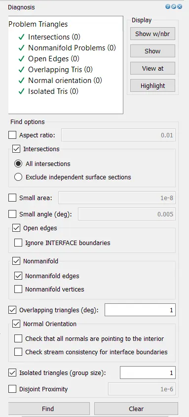
- Geometry diagnosis
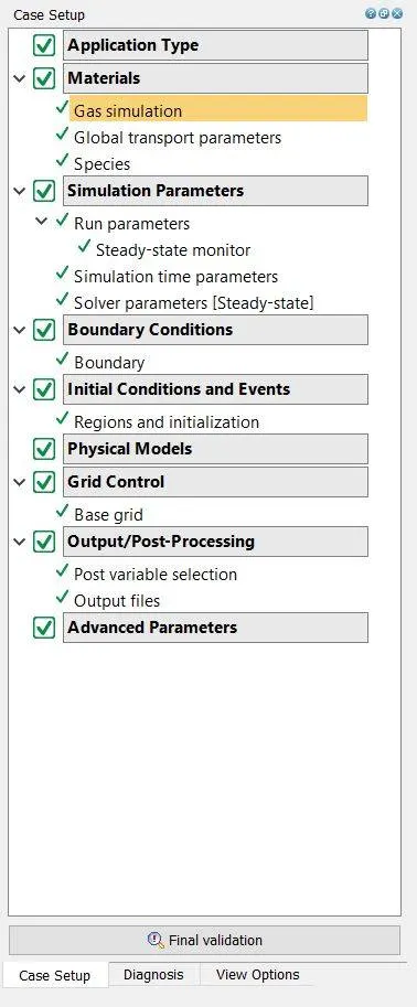
- Simulation Setup/ Case setup:-
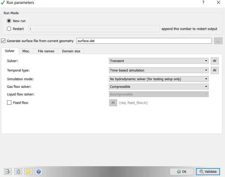
- In Run Parameters two main things to be considered:-
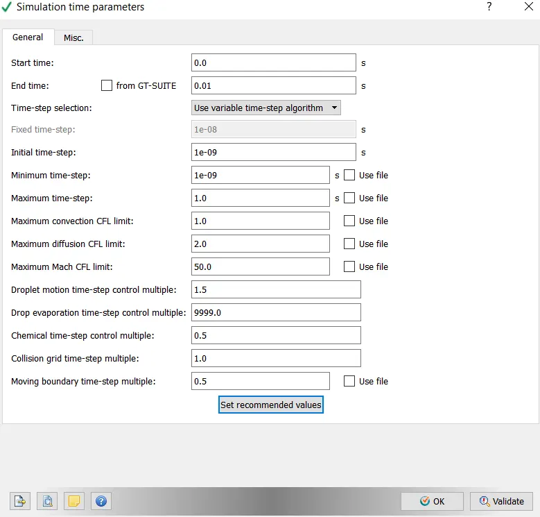
- Post Processing
- Mesh
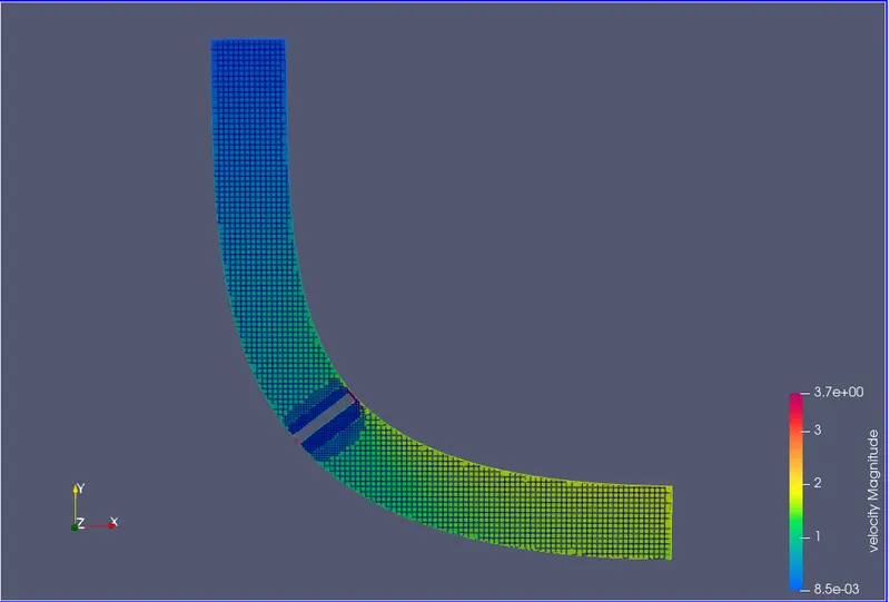
- Velocity contour
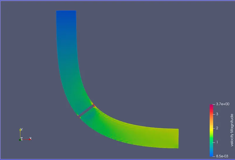
- At inlet, the rate is low due to high static strain and due to the little resistance of the throttle valve through turning 25 diploma attitude, it reasons low pace in inlet vicinity of the throttle frame.
At outlet the rate is better than the inlet however the speed at the outlet would were reached the red vicinity, if the throttle fully open.
- Pressure contour
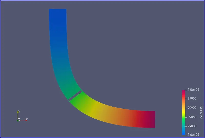
- At the inlet place, from 0.002 secs, the inlet region of pressure is high due to the throttle starting of 25 degree attitude.
At the opening, the strain is pretty low than the inlet.at the inlet going through facet of the throttle, the pressure pretty high because of the strike of excessive pressure air of 150000Pa from the inlet.
on the place of wake vicinity, due to the turbulent eddies, the stress is low on the region of the other facet of the throttle.
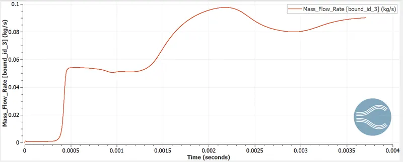
- Mass flow rate plot at inlet
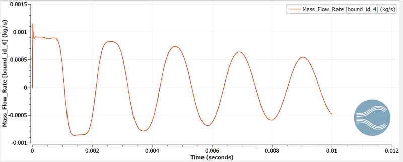
- Mass flow rate at outlet
- Average velocity at Inlet
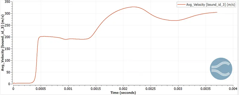
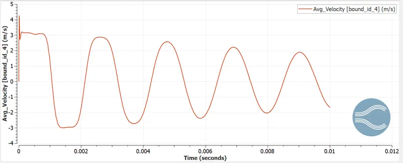
- Via visualizing the contour we can remember that the velocity decreases whilst it moves the throttle plate and due to exchange in throttle position the low stress area created and the go with the flow is circulated and thus the velocity is accelerated
- Average velocity at outlet
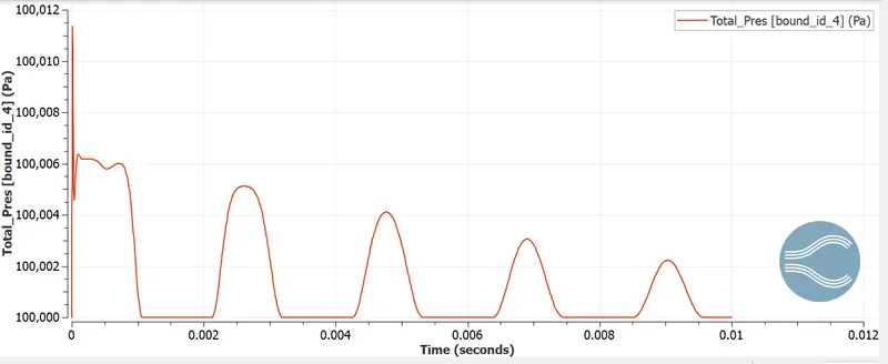
- Pressure at inlet
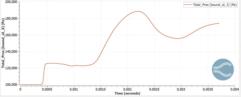
- Whilst the float strikes the throttle the stress is multiplied and the low pressure place is created because of the exchange in throttle function and the waft is circulated and hence the pressure receives decreased within the outlet.
- Pressure at outlet
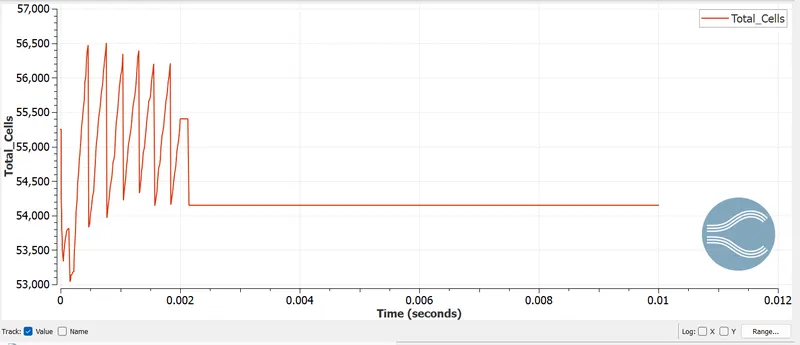
- Total cell count
- Stepwise Explaination
- To setup the given Throttle body geometry case in Converge CFD.
- To simulate the transient country flow of the Throttle frame case through CYGWIN.
- To simulate the Throttle body case physically the usage of PARAVIEW.
- To create and examine the plots of the simulation results via Converge CFD.
- putting in the case in Converge CFD:
- Open Converge CFD and click New project. click and drag the given Throttle body geometry case.
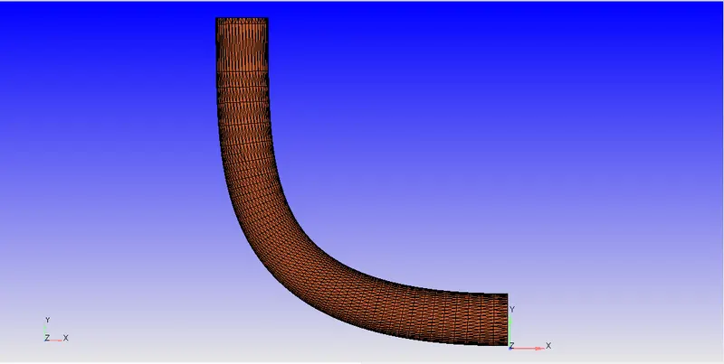
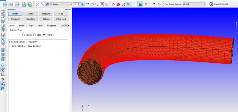
- check the scale of the geometry with respect to Converge CFD that's in meters. If it is in mm scale it to m.The thickness of the geometry has been deleted considering it's miles a regular brief country simulation of a regular air drift and now not a conjugate warmness transfer simulation.
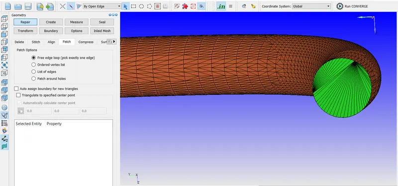
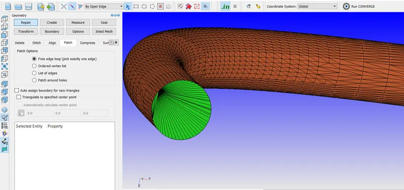
- The inlet and outlet of the pipe has been patched with the aid of restore-->Patch-->click on loose facet loop-->choose the threshold to be patched-->ok. make certain that every one the normals had been orientated within the route of go with the flow that takes area.
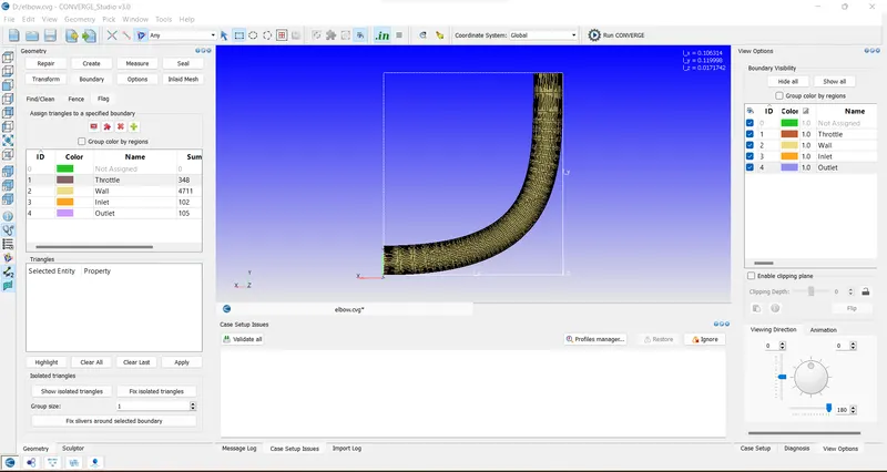
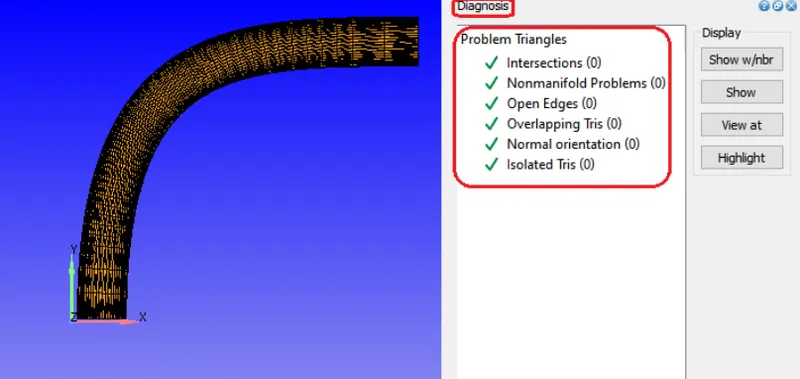
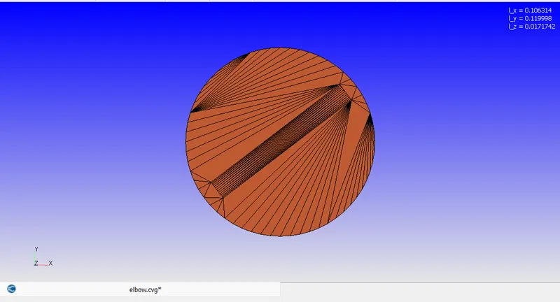
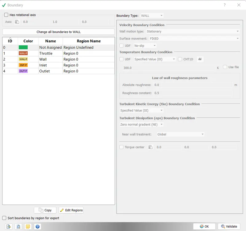
- Within the analysis tab, click discover to check whether the geometry is ideal to simulate as the photograph: the bounds that have flagged are Inlet, Outlet, Elbow wall and throttle.
- The utility type is Time-based totally.
- The pre-defined mixture is Air.
- In Run parameters, brief solver is selected, Time-primarily based kind and the simulation mode is full Hydrodynamic.
make certain to uncheck the shared memory flag and uncheck the consistent country monitor too. - In Boundary situations, the boundary kind of the Inlet as influx, Outlet as outflow, Throttle and Elbow as Wall
- At inlet, the strain boundary condition is the desired price of 150000 Pa, the speed as Neumann boundary circumstance and the Temperature as the specified fee of 300K and the species as N2 of zero.77 and O2 of zero.23.
- At outlet, the pressure and temperature boundary circumstance as precise fee of approximately 100000Pa and 300K and the species are N2 of zero.seventy seven and O2 of 0.23. both the throttle and the elbow boundary type as Wall with regulation of Wall boundary condition because the turbulent flow of fluid gets worried.
- In a Throttle boundary, so as to make the throttle to rotate, make the wall movement type as ROTATING and the surface movement as transferring.
- To calculate the Rotation centre and Rotation axis of the Throttle to rotate, calculate the regular route and centre point of the shaft of the throttle by degree-->direction-->Arc normal-->click on any three vertices of the cylindrical face of the shaft-->observe.
- The cost of arc centre and arc regular has been copied and pasted from the message log as rotation centre and rotation axis because the path of ordinary of the shaft of the throttle and the route of the rotation axis and the rotation centre is equal.
- For Rotation price of the throttle, Use record and click + to feature the limitations and at 2nd zero, the perspective is 0 and at 002 sec, the angle is 25deg.ensure that the Turbulent kinetic energy (tke) boundary circumstance is in Neumann boundary condition.
- The Region0 has been created by means of areas and Initialization with the atmospheric stress of 101325Pa and temperature as 300K and it’s been assigned to all of the barriers.
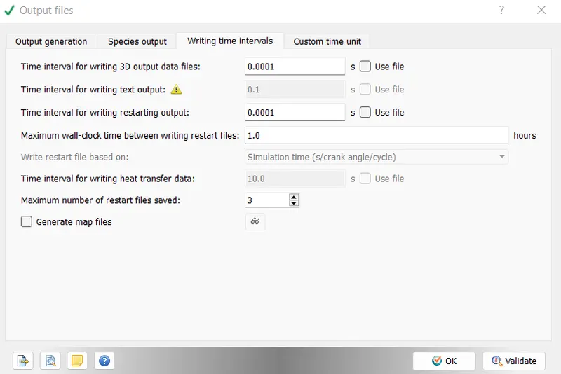
- In Simulation time parameters, the start time is 0 sec, the quit time is 0096 sec.The preliminary and minimal time step is 1e-nine sec. and the most time step is 1 sec.
- In Turbulence Modelling, the RANS RNG k-epsilon version has been used.
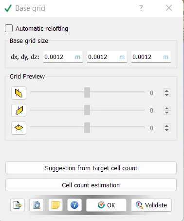
the base grid of 2e-03m and with the default base grid, the fixed embedding kind has additionally been enabled considering the fact that the gap between the throttle plate and the throttle frame wall is small or for you to get feasible finer effects across the throttle for the reason that variables like stress and speed could be various broadly. - In fixed embedding, click upload and Entity type as Boundary and Boundary id as throttle in everlasting mode with a scale of 3 and embed layers of two.it's also vital to note that neither the base mesh size need to be smaller nor the embedded mesh size have to be large or Vice versa.
- Specify the Mass fraction of N2 and O2 in submit variable selection on the way to get a finer simulation results in PARAVIEW and the glide or presence of N2 and O2.Then, the entire documents were simulated in CYGWIN .
- Calculation of End time of simulation:
-
The characteristic length of the given geometry is approximately taken as 0.2m.
The average velocity of the given geometry is 4.05 m/s.
The Flow through time = characteristic length / average velocity.
The Flow through time = 0.2/4.05 =0.04938 sec.
- Conclusion and observations
- From the above contours it's far clean that, on giving the excellent mesh to the valve the contours appear extra info and the results are fairly accurate.
- The glide thru the throttle function is greater correct because the mesh generated alongside the throttle role is subtle (having extra cells surrounding the valve) i.e. by using presenting 2embedded layers and a scaling of 3 to the mesh.
- The contours display that, there may be a restriction to the flow of intake air that is caused by throttle plate.The inflow mass drift charge is balanced by means of the outflow fee.
- If there may be much less restriction inside the glide , then there's a lower loss in power. hence due to this the rate at outlet will increase.
- As we've a shifting mesh, variety of cells generated are more and for this reason simulation time is excessive.
- The brief simulation-glide over a throttle body is performed the use of converge CFD.
- With finer refinement of mesh the accurate results are received .
- Diverse plots, contours and animations are generated to study the go with the flow over a throttle frame.
- Throttle motion is also captured for better knowledge of go with the flow.
- Google drive link for animations
https://drive.google.com/drive/folders/17OrdqE25jKSsREcyCq3FVLSKG148C--o