Week 4-1D Element Creation Challenge
Objective:
Mesh the Given component with the Size of 5 Units. Create 1D elements on the following component with given cross-section and DOF
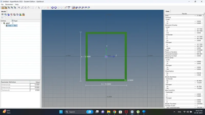
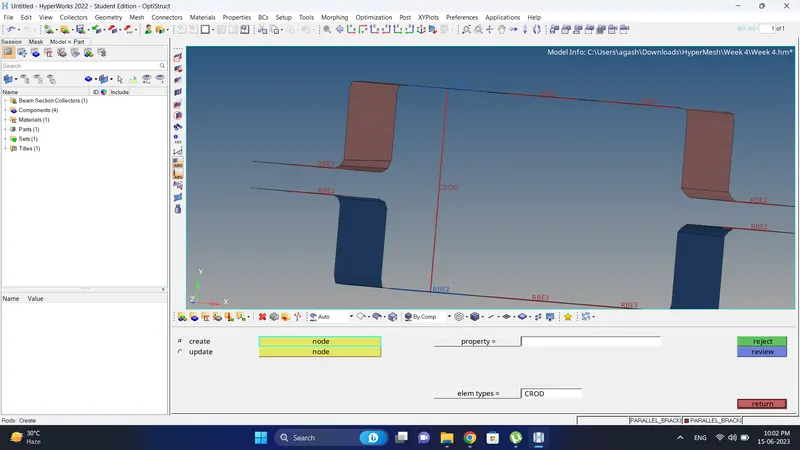
a. Rod element:- Translational DOF should be Constrained with RBE2 link
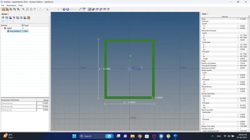
Cross-Section: BOX- Dimension a= 12 mm
dimension b=10 mm
Thickness t= 0.75 mm
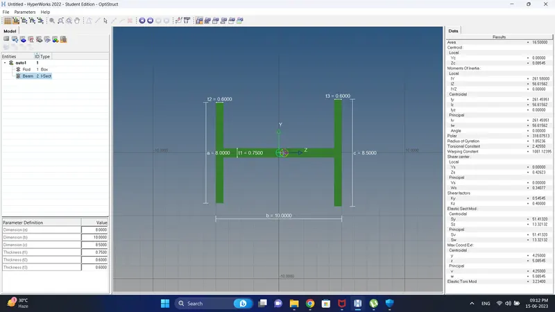
b. Beam element:- All DOF should be constrained with RBE3 link
Cross-Section: I Section- Dimension a= 8 mm
Dimension b= 10 mm
Dimension c= 8.5 mm
Thickness t1= 0.75 mm
Thickness t2= .6 mm
Thickness t3= .6 mm
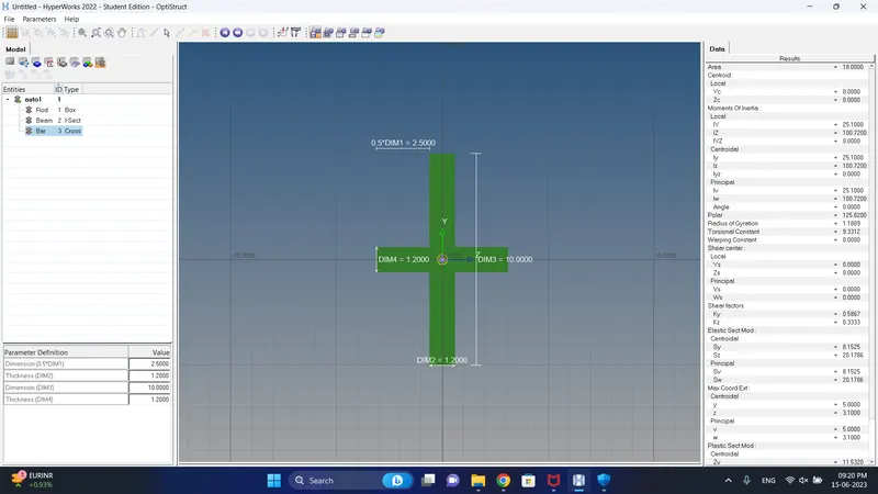
c. Bar element:- Constrain only x and y DOFs With RBE3 link
Cross-section: X section- Dimension DIM1= 5 mm
Thickness DIM2= 1.2 mm
Dimension DIM3= 10 mm
Thickness DIM4= 1.2mm
d. & e. Apply the mass of magnitude 10 with the RBE2 link
f. Join the two components with Spring elements
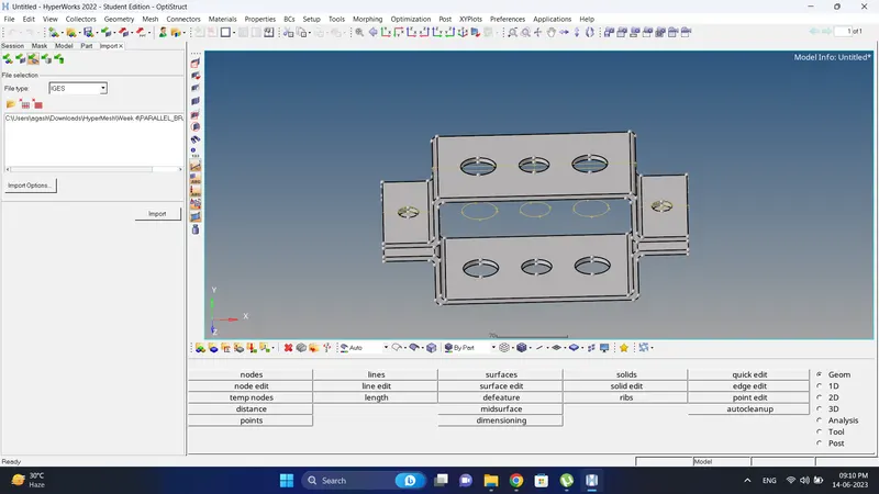
Cad Model Image:
Initial
Procedure:
1. Import the component.
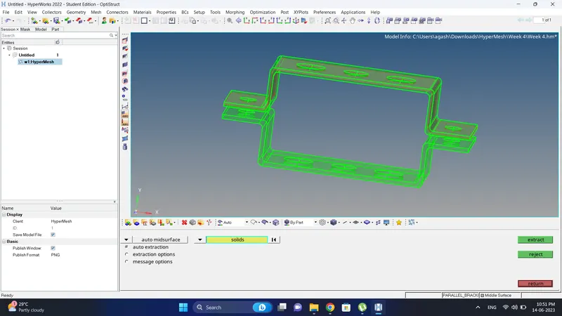
2. Go to the Geometry-Midsurface, select one component and create mid surface.
Do the same with other.
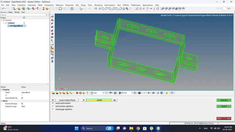
3. Rename the mid surface.
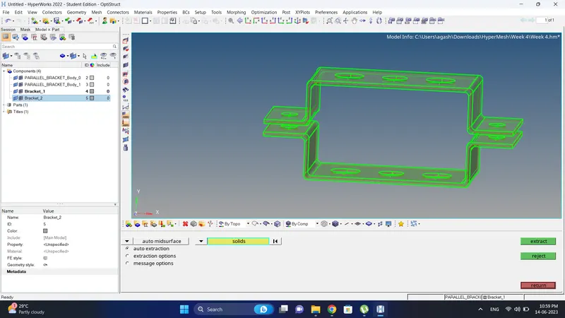
4. Hide the solids, Create a material and Rename as steel.
Note: Since properties are not given no need to edit it.
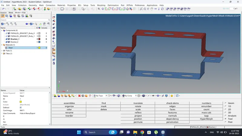
5. Create washer near the holes by going to Geometry-Quick edit-Washer split, give offset value as Target length befor creating and create the washer.
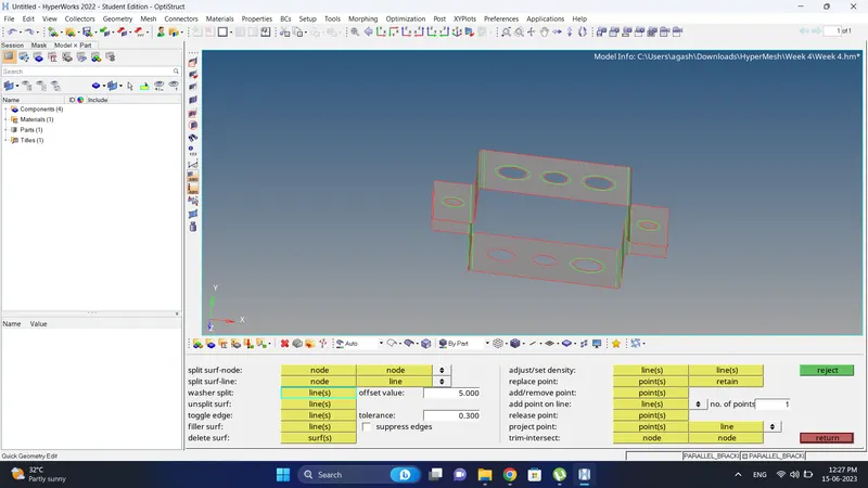
6. To create 2D mesh go to 2D-Automesh, give target length, sellect all the component and create a mesh.
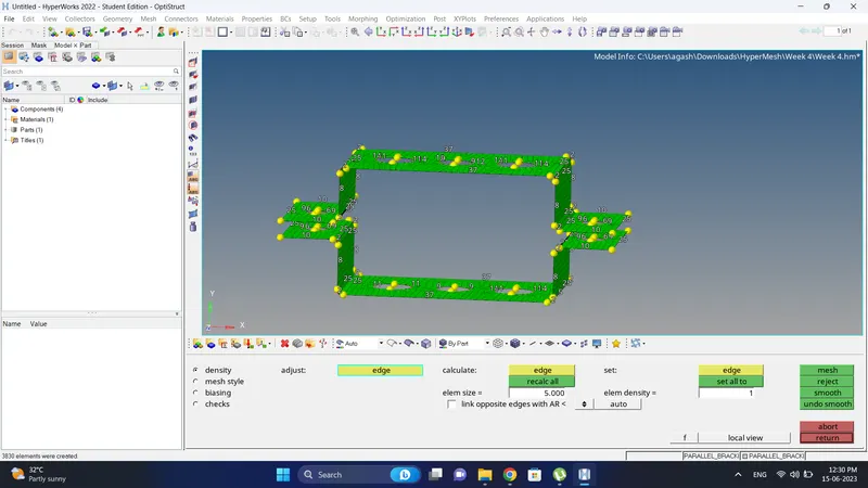
7. Near all washer/hole area improve mesh by increasing and decreasing the number.
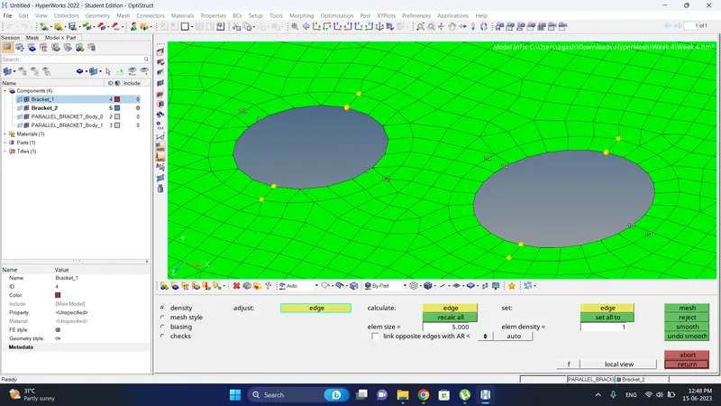
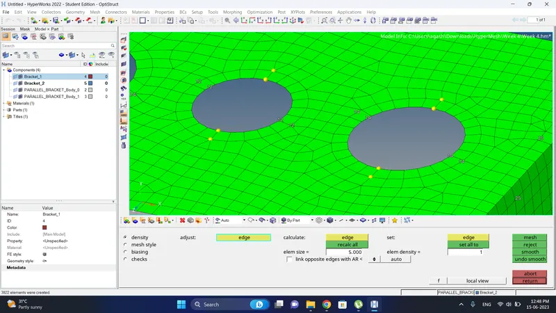
8. After that 2D mesh is complete.
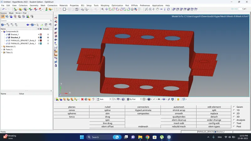
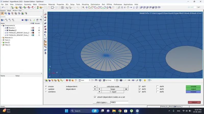
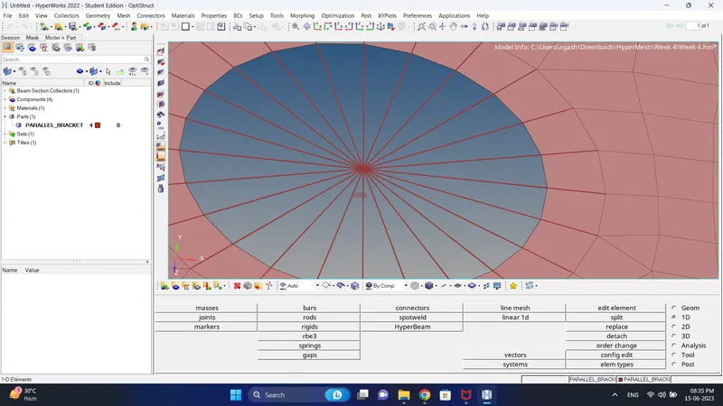
9. After that create a RBE2 Element by going to Geometry-Rigids, select nodes, DOF and create RBE2 element.
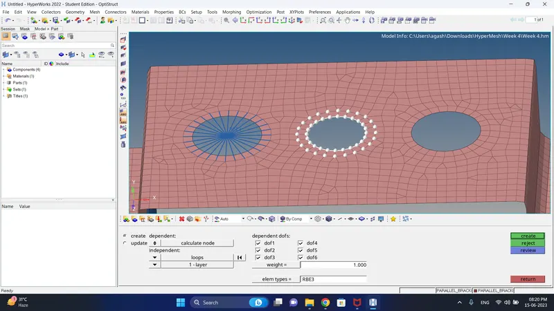
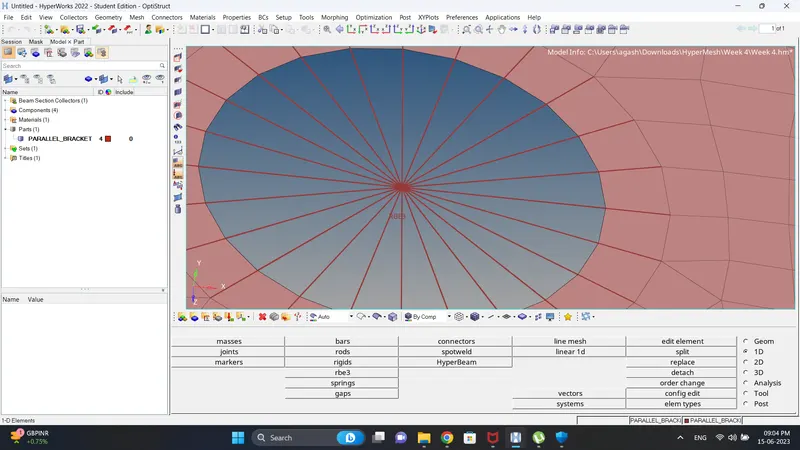
10. To create RBE3 go to the 1D-RBE3, select nodes and create RBE3 element.
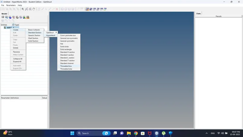
11. To represent Rod, Beam and Bar element we need to create the different cross section for them.
Go to the Hyperbeam view, create different cross section, give dimensions and rename them as per element.
12. To create rod element go to 1D-Rods, change element type to CROD, select nodes and create rod element.
13. Create a property rod, beam and bar.
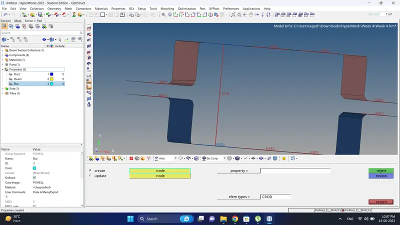
14. Go to the rod property change card image to PROD, assign the cross section and update property of rod.
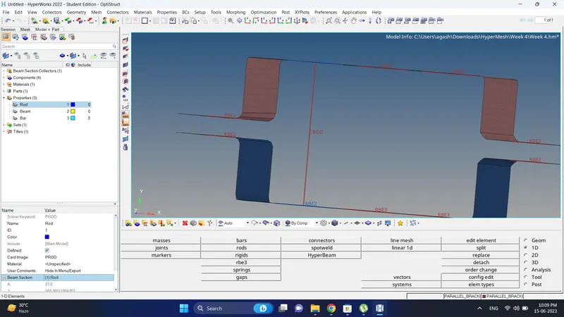
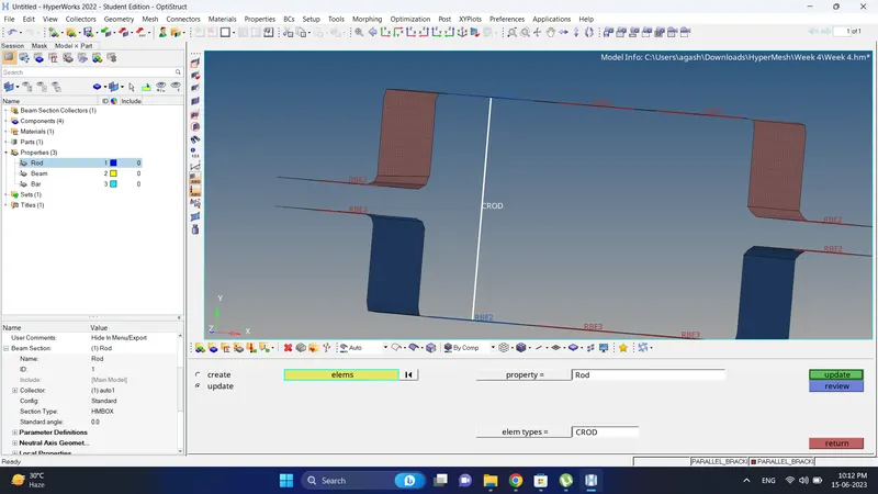
15. To see the cross section go to element representation and change it to 1D Deatailed element representation.
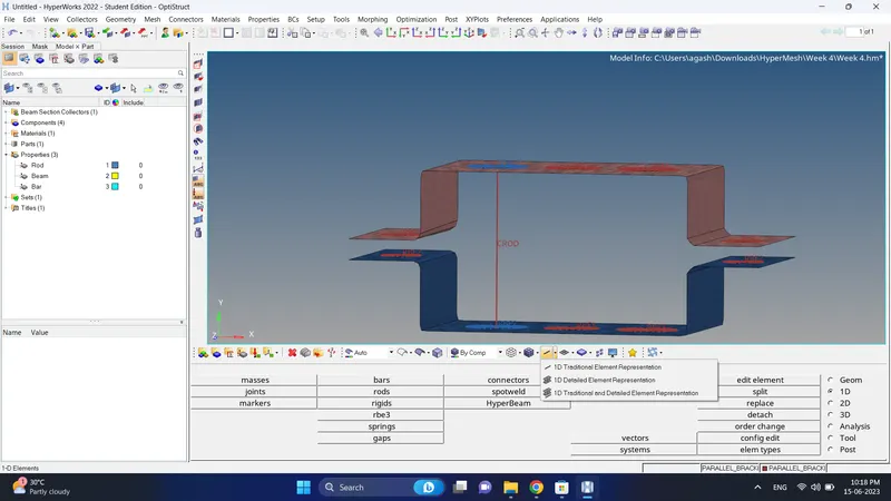
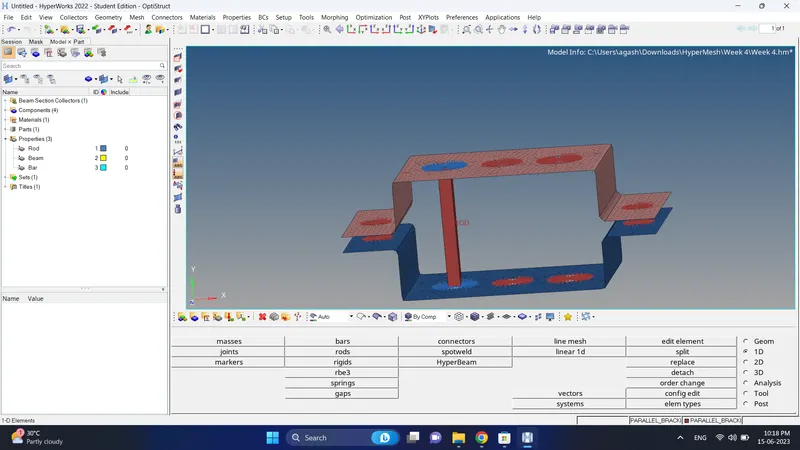
16. To create beam element go to 1D-Bars, change element type to CBEAM, assign beam property, select nodes and create a beam element.
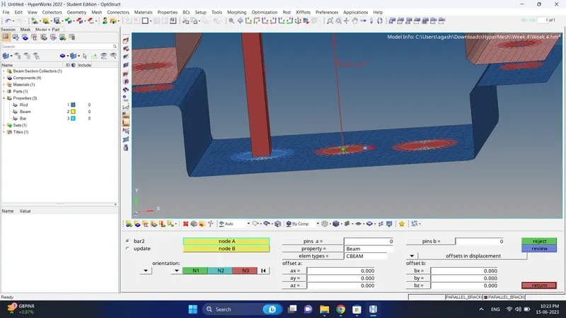
17. Got to beam property change card image to PBEAM and assign Cross section.
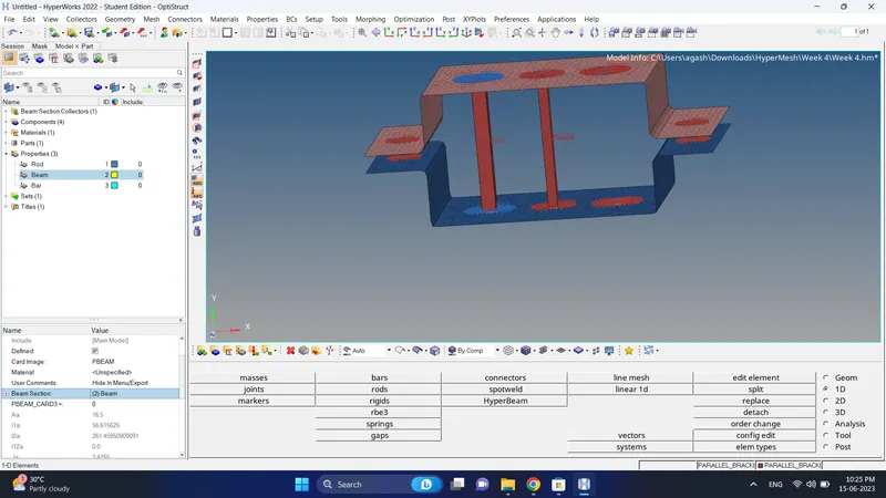
18. To create bar element go to 1D-Bars, Change element type to CBAR, assign property, select nodes and create Bar element.
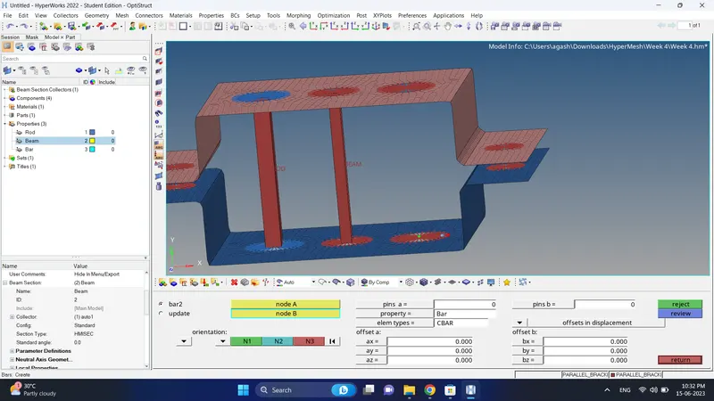
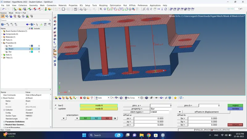
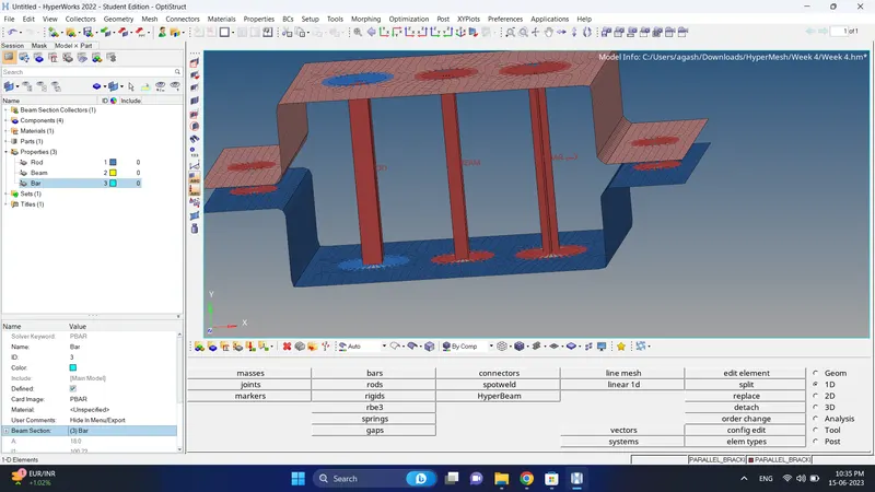
19. Go to bar property, change card image to PBAR and assign cross section.
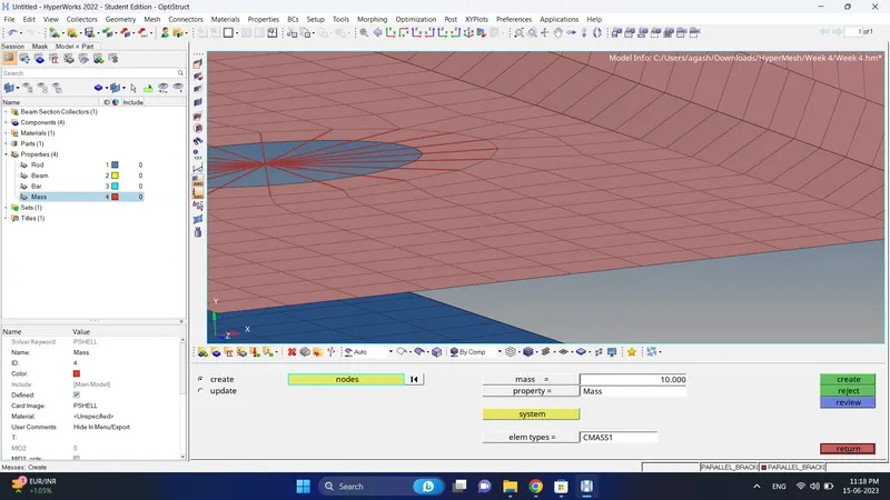
20. Create property for masses.
To assign mass go to 1D-Masses, give mass magnitude, Change element type to CMASS1, select node, assign property and create it.
Do the same for other also.
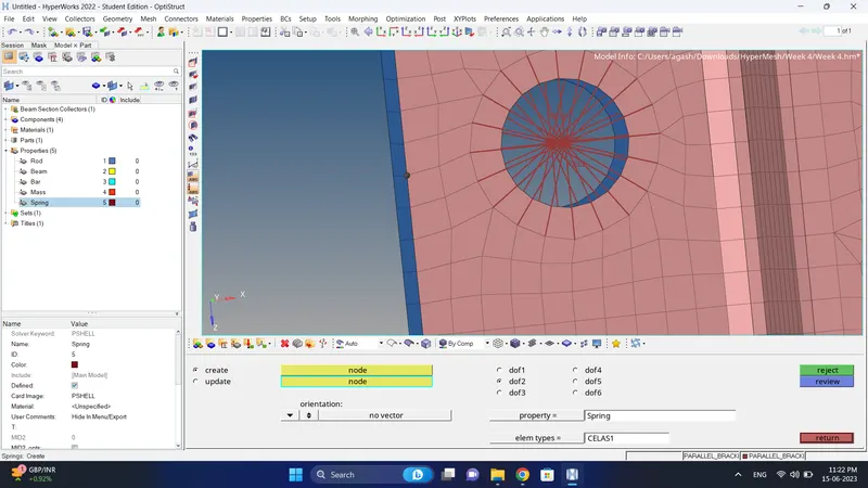
21. Create a property for spring and change the card image to PELAS.
To create spring element go to 1D-Spring, select nodes, assign property and create it.
Do same for other side also.
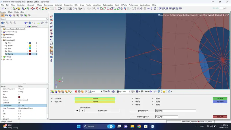
22. Do the final check.
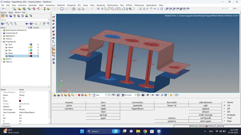
Final Model Image:
Results:
- Meshing the Given component with the Size of 5 Units is done successfully.
- Creation of 1D elements of the following component with given cross-section and DOF are done successfully.a. Rod Element.b. Beam Element.c. Bar Element.d. Applying the mass.e. Applying the mass.f. Using spring element joining two component.