Week 4-1D Element Creation Challenge
CHALLENGE 3: 1D ELEMENT CREATION
AIM:
The given model is to be meshed and to assign pre-defined 1D elements with cross-sectional parameters.
CAD MODEL:
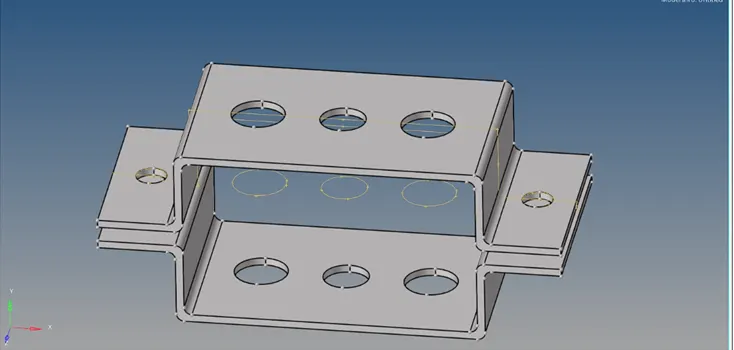
PROCEDURE:
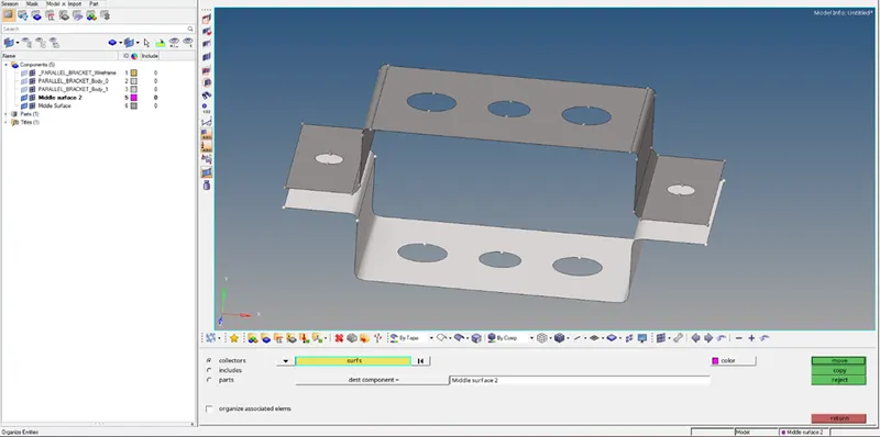
- Select the Midsurface panel from Geom menu.
- Select solids to extract the mid-surface.
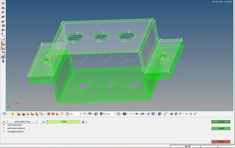
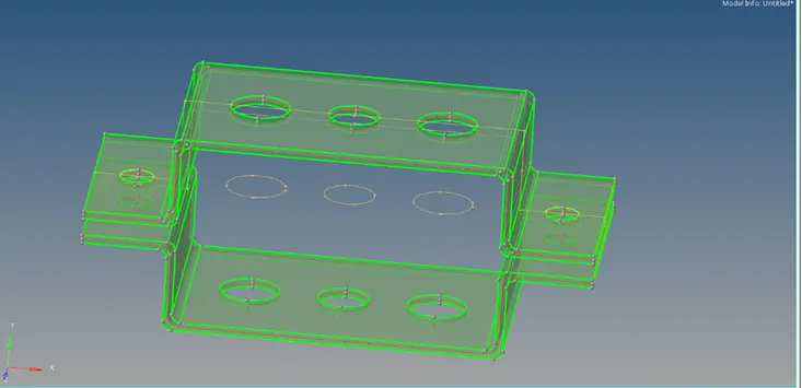
- The created mid-surfaces are of two separate brackets, but they exist as a single component in Components list.
- This can be corrected by creating new component For the second middle surface.
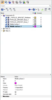
- Use Organise panel to assign the mid-surface to the component list.
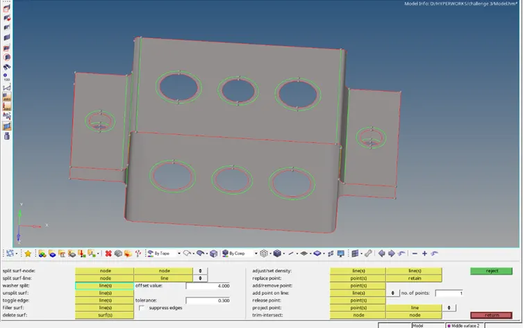
- Create washers around the holes using Quick Edit panel.
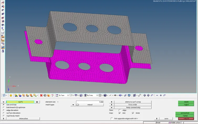
- Mesh the mid-surfaces by using Automesh panel in 2D menu, input the required element length.
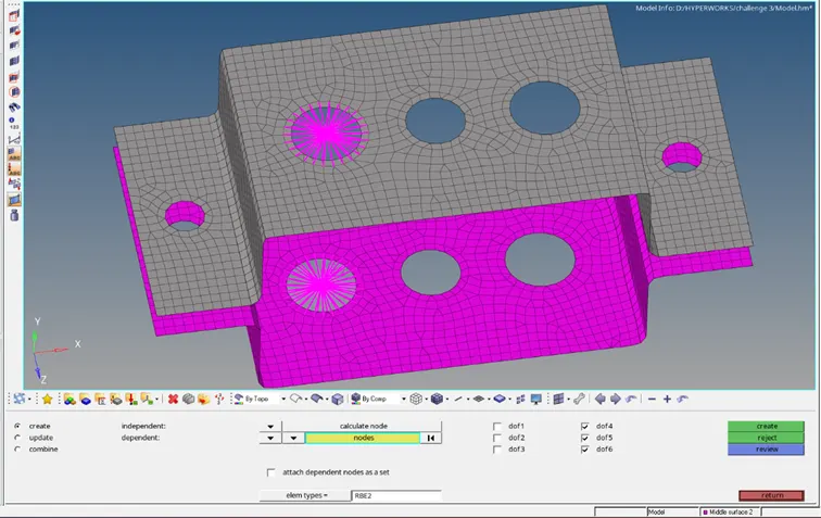
- RBE2 links (Translational DOF constrainted) are created by Rigids panel from 1D menu.
- Assign a rod element between RBE2 links.
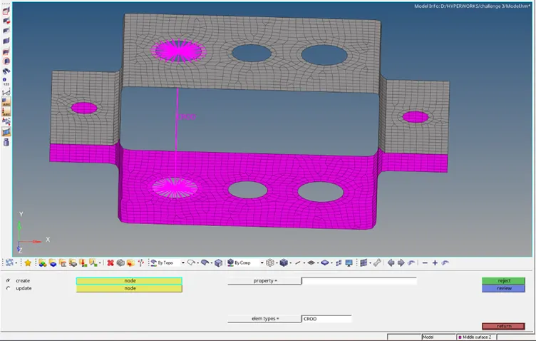
- Next, create RBE3 element (all DOF constrainted) links using RBE3 panel.
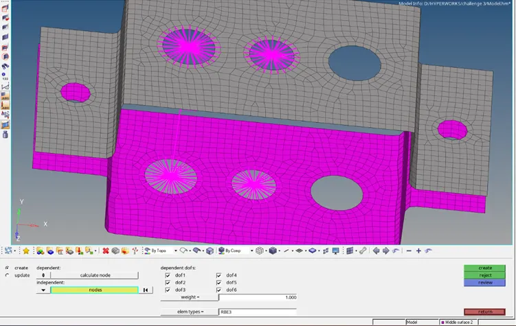
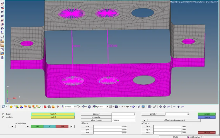
- Assign a beam element between RBE3 links.
- Similarly, create RBE3 element (X and Y DOF constrainted) links using RBE3 panel and assign a bar element between RBE3 links.
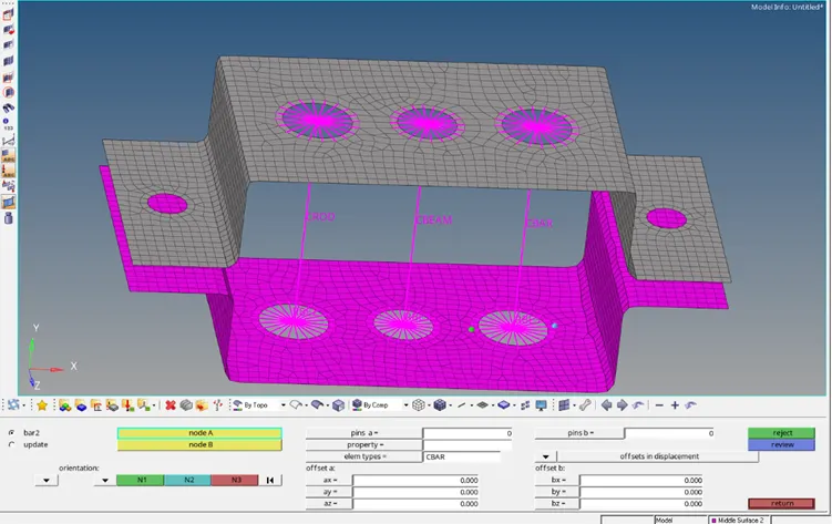
- Open HyperBeam panel to create the required cross-sections by switching to HyperBeam View.
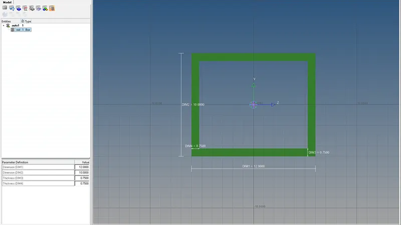
- Create box cross-section for the rod by defining the parameters.
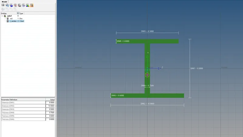
- Create I cross-section for the beam by defining the parameters.
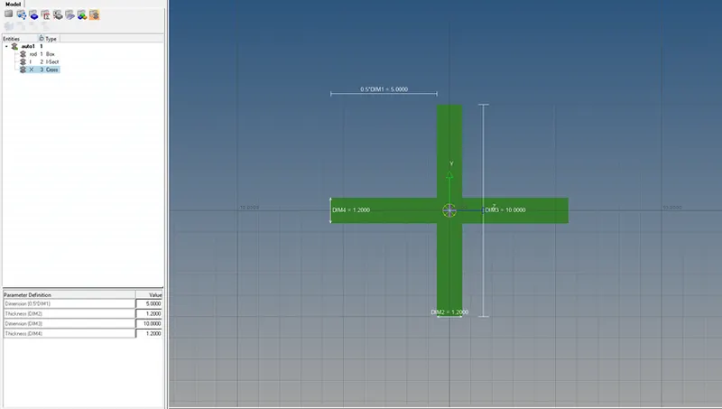
- Create X cross-section for the bar by defining the parameters.
- Switch back to Model View.
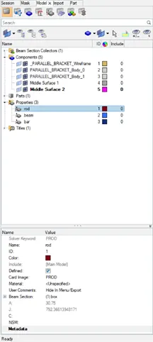
- Create separate property list for Rod, Beam and Bar by assigning their respective property card and cross-sections.
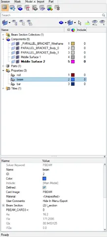
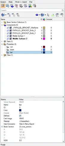
- Update each of the elements with their respective property.
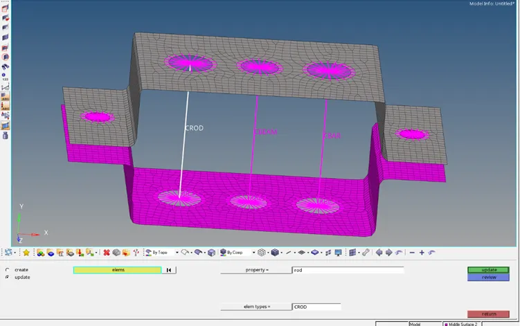
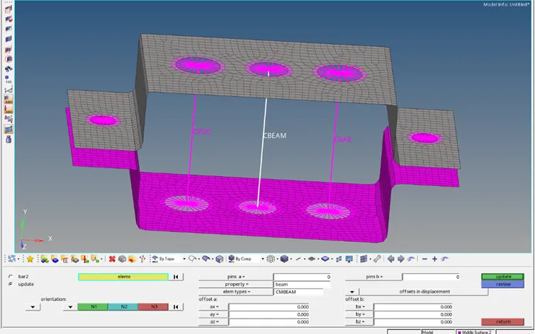
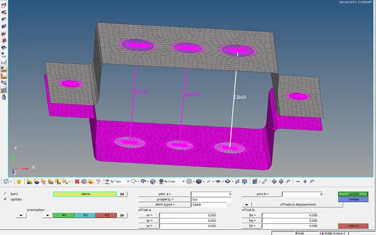
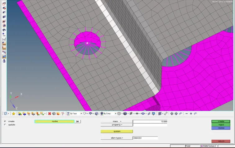
- Create RBE2 link on the side holes.
- Assign mass (CMASS1) of 10 units to the RBE2 link.
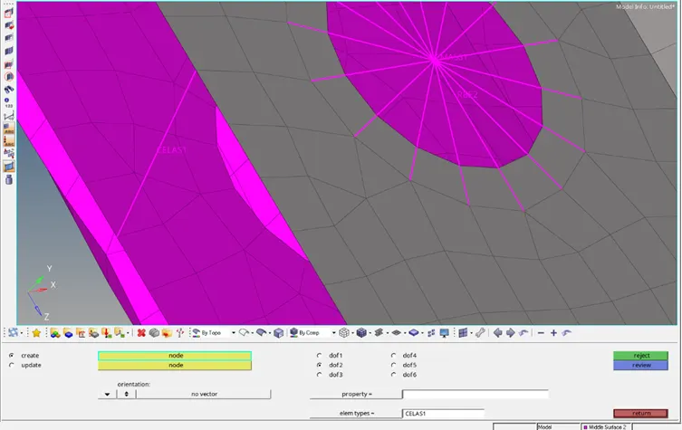
- Connect both the mid-surfaces using Spring element (DOF in Y-axis only).
Final Model:
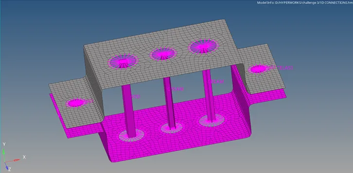
RESULT:
The model has been meshed by creating mid-surfaces and the 1D elements were created by assighning cross-sections and other parameters.