Week 4-1D Element Creation Challenge
Report on 1D Element Creation Challenge
AIM:-Mesh the Given component with the Size of 5 Units. Create 1D elements on the following component with given cross-section and DOF
For that we to follow the following steps
1) First we have to create mid surface, since geometry is simple and clean , goto Geom>mid-surface>auto mid surfaces>surfs>select diplayed>create , mid surfaces is created, along with create a property for upper and lower bracket and assign to them
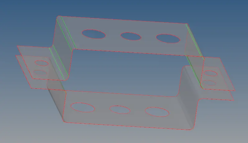
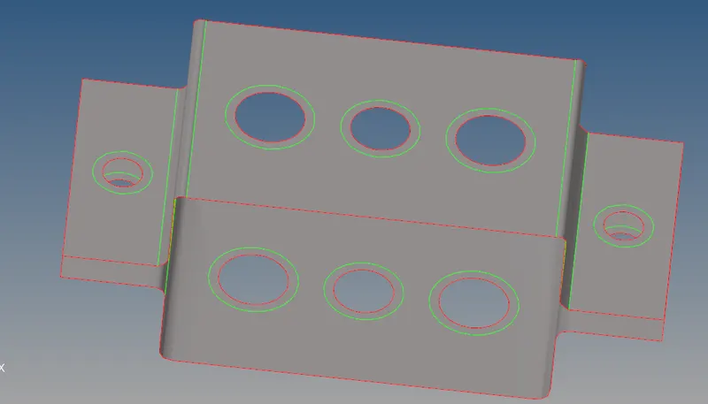
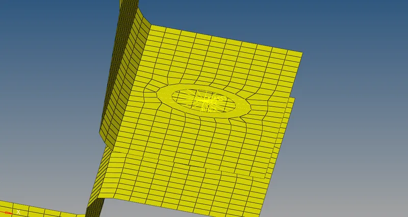
2) create washer splits goto Geom>quick edit>washer splits>offset value=5, it will created,
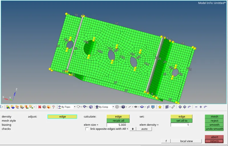
3) Now create a mesh on the mid surface goto 2D>automesh>select the surface>give element size =5>click on mesh
4) Now create 1D element, so first create RBE2 or Rigid link on at position a,d,e as mention in question for that goto 1D>Rigids>create>change first nodes to calculate nodes and second node to multiple nodes>now select the nodes by path>click on create RBE2 link will created
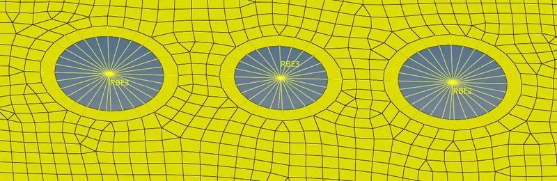

similarly we can do for RBE3 at b and c position and create RBE3 link
5) Now we have to give mass of magnitude 10 to point d and e for that goto 1D>Masses>select nodes>give magnitude 10>click on create, mass will assigned at that nodes of magnitude 10

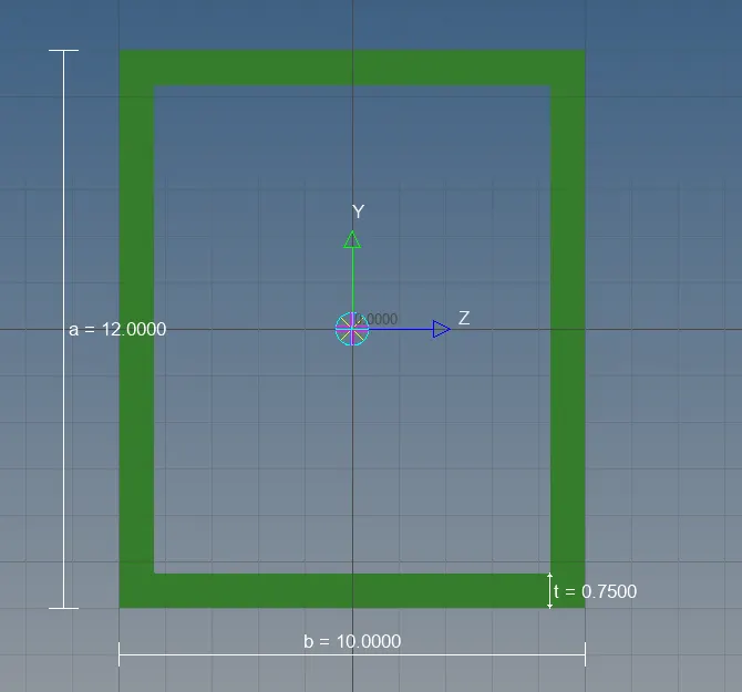
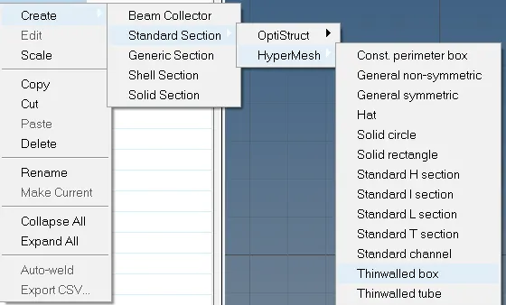
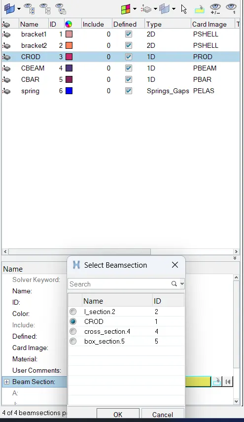
6) Now we create Rod element (cross-section = box, dimension a=12mm,b=10mm,t=0.75mm) between the RBE2 link at position a for that goto 1D>Rod>element type=CROD>select nodes, CROD will create , now goto hyperbeam>standard selection>hyperbeam>thinwalled box>create hyperbeam view will open , give the dimensions, now create the property for CROD element , click on property goto beam section click on that , beam section will open select the CROD and click ok, now right click on the crod property >assign>click on the rod element from GUI area , now crod will assign to the property
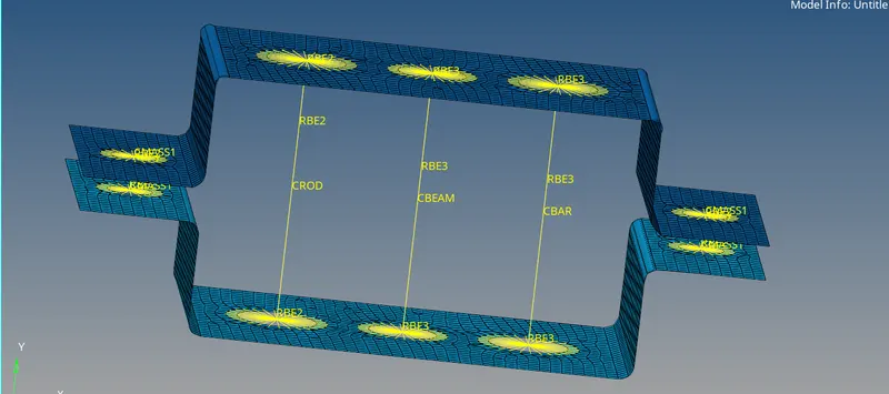
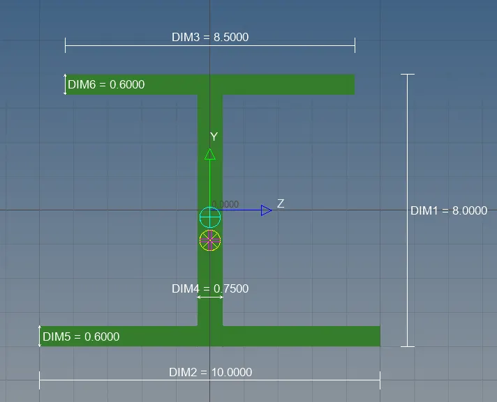
7) Similarly we can do it for beam element (Cross-Section: I Section- Dimension a= 8 mm Dimension b= 10 mm Dimension c= 8.5 mm Thickness t1= 0.75 mm Thickness t2= .6 mm Thickness t3= .6 mm) between the RBE3 link at position b for that goto 1D>bar>element type=CBEAM>select nodes, CBEAM will create now goto hyperbeam>optistruct>select I section> create hyperbeam view will open , give the dimensions, now create the property for CBEAM element click on property goto beam section click on that , beam section will open select the I section and click ok, now right click on the CBEAM property >assign>click on the beam element from GUI area , now CBEAM will assign to the property
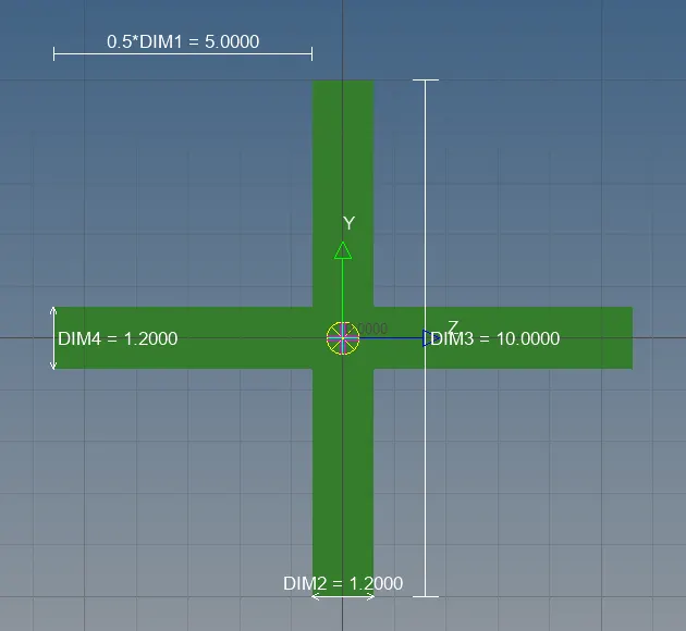
8) Similarly we can do it for BAR element (Cross-Section: X- Section- Dimension DIM1= 5 mm Thickness DIM2= 1.2 mm Dimension DIM3= 10 mm Thickness DIM4= 1.2mm) between the RBE3 link at position c for that goto 1D>bar>element type=CBAR>select nodes, CBAR will create now goto hyperbeam>optistruct>select X section> create hyperbeam view will open , give the dimensions, now create the property for CBAR element click on property goto beam section click on that , beam section will open select the X section and click ok, now right click on the CBAR property >assign>click on the bar element from GUI area , now CBAR will assign to the property
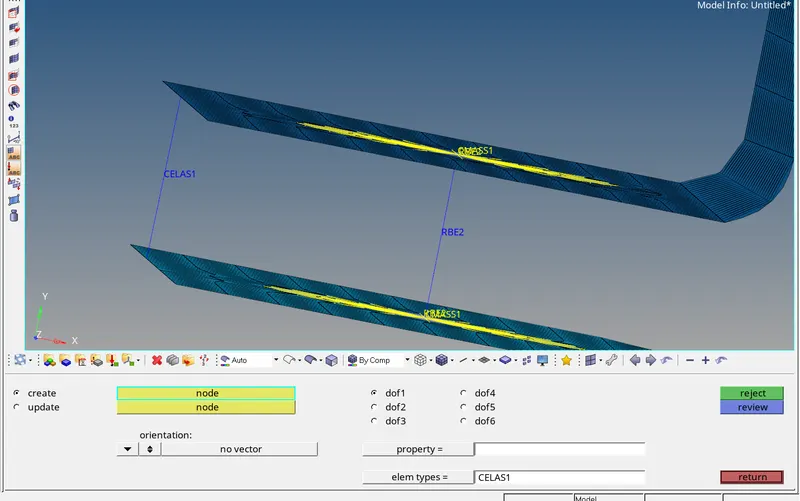
9) Create springs at the extreme end at position f as per question goto 1D>springs>select element type=CELAS1>select the nodes at extreme end of upper bracket and lower bracket at one side, now spring will created
Conclusion :- Here we are focusing on 1D Element Creation