Week - 5 - 2D meshing for Plastic components
Project report on Plastic Bottle Cap model
Aim :- For the given Plastic Bottle Cap model, Take the mid surface for all the components after checking the geometrical errors and mesh the mid surface with the given element Quality criteria and provide appropriate thickness. (Refer the table Below for the Quality criteria)
For the given geometry we have to set quality criteria and mesh parameter
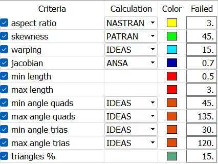
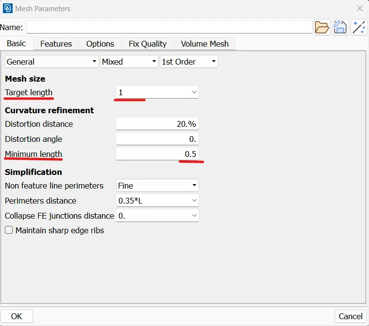
For that we have to follow the following step :-
1) First we go to mesh module under this perimeter we select length option after left clicking on that option we select the whole model by midle mouse click we set a value 1 and click ok. By doing this in the geomtry the distance between any two nodes will be 1 unit
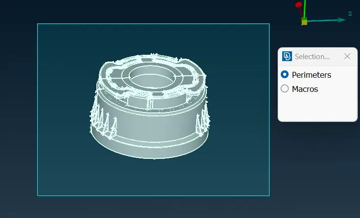
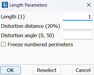
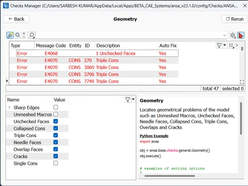
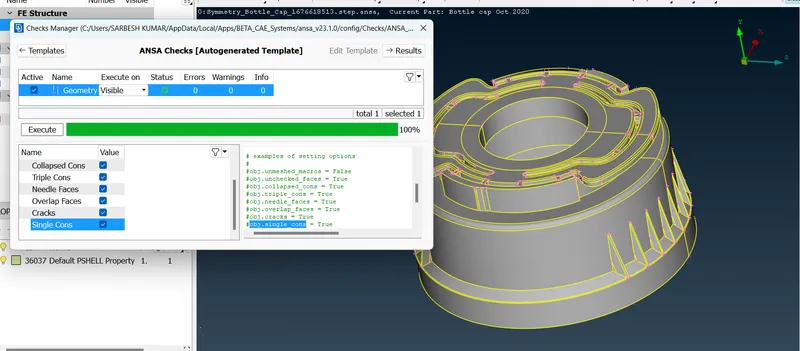
2) After that again we go to check >geometry>execute there are so many errors found one by one we resolve the errors and again go for check >geometry>execute and repeat this cycle until all the geometrical errors are eliminated
3) After geometrical cleanup, we have to do Mid-surface extraction for that we go to topo>faces>offset(select the face), by clicking middle mouse button we give the value according to the given direction of arrow on the face. e.g if the arrow in positive y- direction we assign negative value which is equal to half of the thickness of the model along with negative sign.
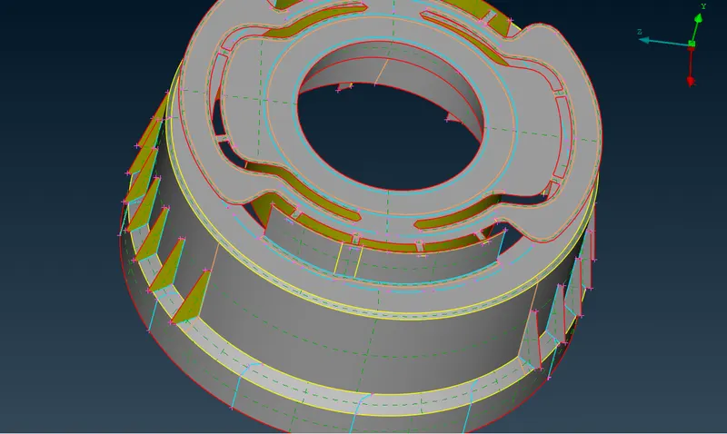
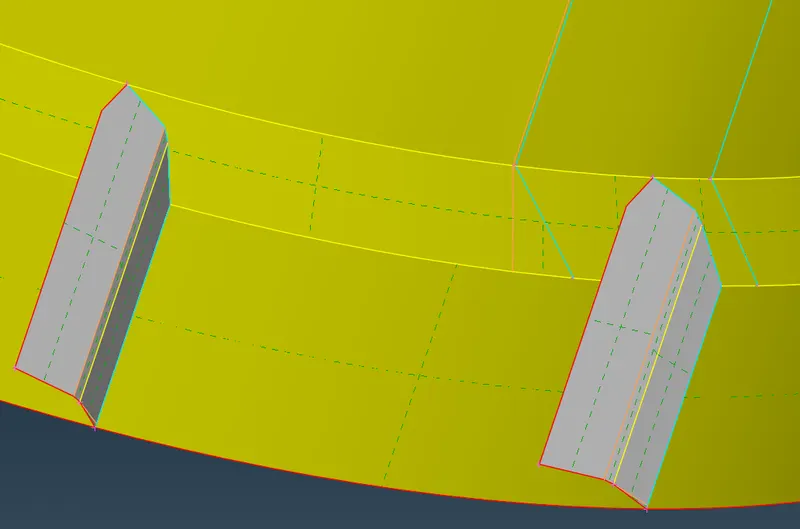
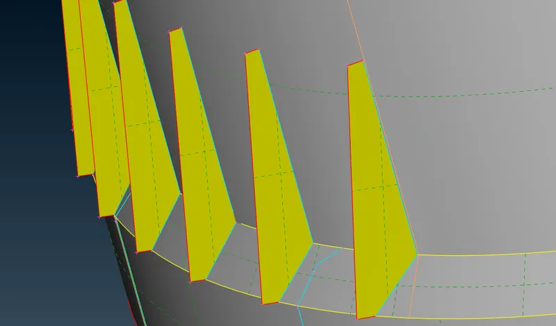
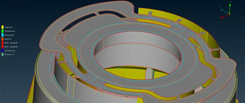
we have also use curve option e.g Topo>curves>cons2curve, Topo>curves>middle , Topo>curves>create
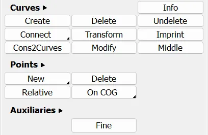
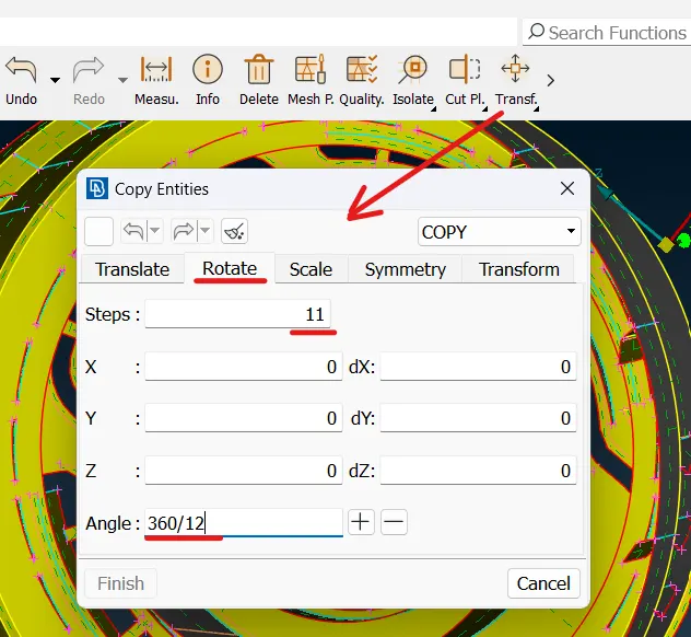
we also use point option Topo>points>onCOG in this option we use COG to define centre of gravity about which we can perform Rotation (transform>copy>rotation), it will copy the entities in circular fasion about COG
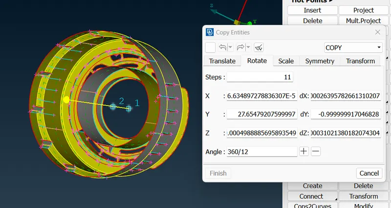
4) After that new mid surface will be created in thhe midle of the thickness of the plate
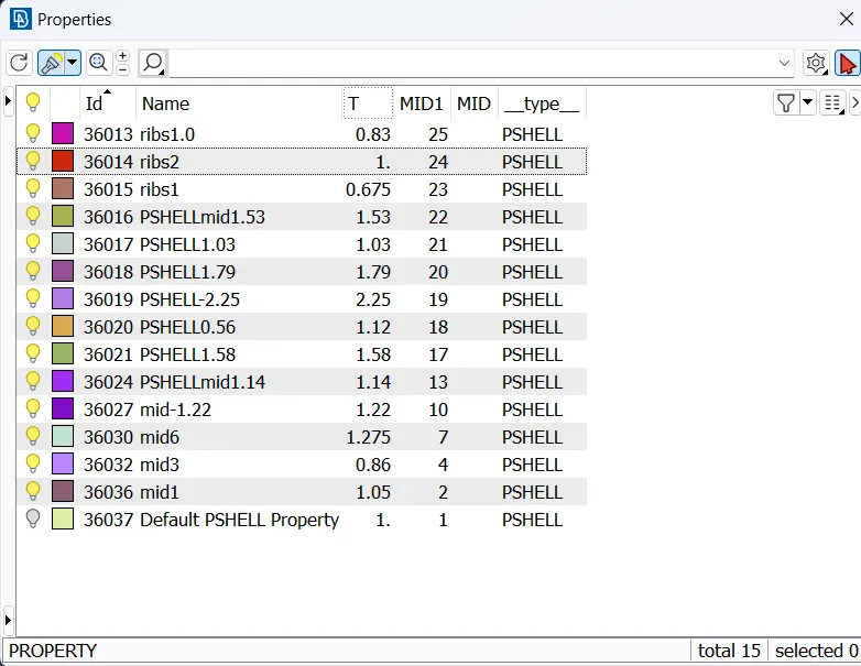
5) We have to assign property id for that we goto Topo>Faces>Set PID, under this a property window will open under this we create a new pid after that a particular id is set up for each part seperately sothat we can assign thickness because it is a plastic component having variable thickness.
Few points must be Obey during the meshing
- No Tria element on the edges (free edge , share edge ,non- manifold edges, )
- No opposite trias in the Mesh
- Not trias should touch each other (no back to back trias)
- No trias must touch features (Embosses,Fillets , Holes, Logos, Dog Houses, Weldings etc.)
- There should be an even number of nodes on the holes opening
- No rotational quads
- No pattern Trias
6) Meshing Part:-
After geometrical cleanup, we have to do Mid-surface extraction for that we go to topo>faces>mid surface>skin(select the model), by clicking middle mouse button we give the value according to the given direction of arrow on the face will automatically taken by ansa
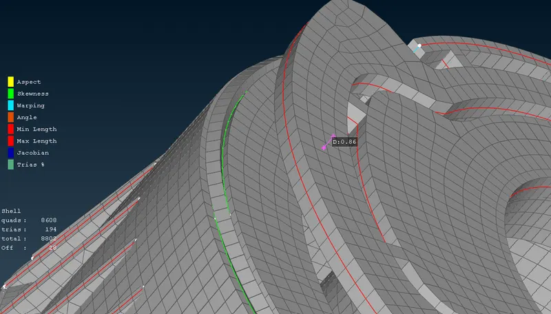
- after that we goto the mesh module under classic mesh Mesh>Mesh Generation>Best by clicking middle mouse mesh is generated here under Element option
- we are using Reconstruction (mesh>shell mesh>Reconstruction) and Smooth (mesh>shell mesh>smooth) very frequently and if there are more tria then we have to go for manually
for that we use split (mesh>elements>split), swap (mesh>elements>swap), join (mesh>elements>join)
- Near the ribs attachment region and in some few region we have to compromised with quality issue due tripple cons , tripple can not be suppress
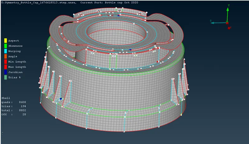
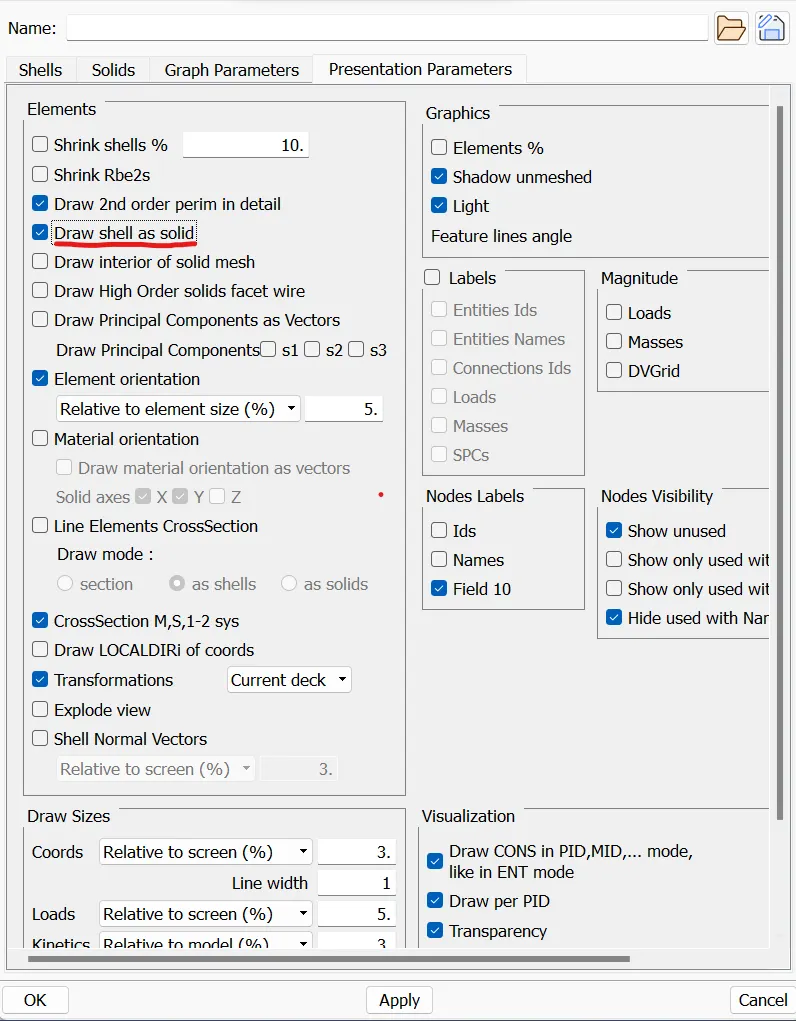
7) Assigning Thickness is allready done during creation of PID, Now we have to check Draw shell as solid (quality criteria>presentation parameter>draw shell as solid)
Conclusion:- Here we learn different techniques used during Mid surfacing ,like Rotation option for copy in circular fasion, cuvres> COG,etc, in this case meshing is not a difficult task and this model is also a complicated one , so here proper observation during Mid surfacing is required
Thank You