Week 4-1D Element Creation Challenge
AIM:
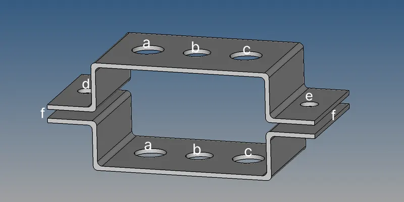
To mesh the given component and create 1D elements of components such as rod, beam, bar and spring with given cross-section and DOF.
COMPONENTS:
a. Rod element:- Translational DOF should be Constrained with RBE2 link
Cross-Section: BOX- Dimension a= 12 mm
Dimension b=10 mm
Thickness t= 0.75 mm
b. Beam element:- All DOF should be constrained with RBE3 link
Cross-Section: I Section- Dimension a= 8 mm
Dimension b= 10 mm
Dimension c= 8.5 mm
Thickness t1= 0.75 mm
Thickness t2= .6 mm
Thickness t3= .6 mm
c. Bar element:- Constrain only xand y DOFs With RBE3 link
Cross-section: X section- Dimension DIM1= 5 mm
Thickness DIM2= 1.2 mm
Dimension DIM3= 10 mm
Thickness DIM4= 1.2mm
d& e. Apply the massof magnitude 10 with the RBE2 link
f. Join the two components with Spring elements
PROCEDURE:
- First the IGES is imported using ‘import geometry’.
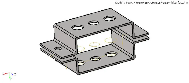
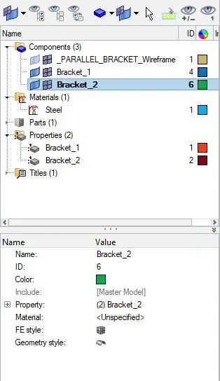
- Then, the mid surface of one solid is created by selecting ‘midsurface’ in ‘’geometry” (skin offset option is used to create mid surface). The name of component is changed to ‘Bracket_1’. The same procedure is done to create second mid surface and it is named as ‘Bracket_2’
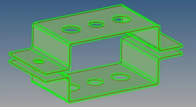
- Now, with the use of ‘delete’ option the both the solids are removed and their names are deleted from component section.
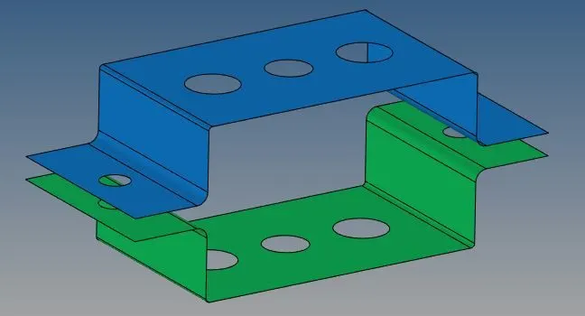
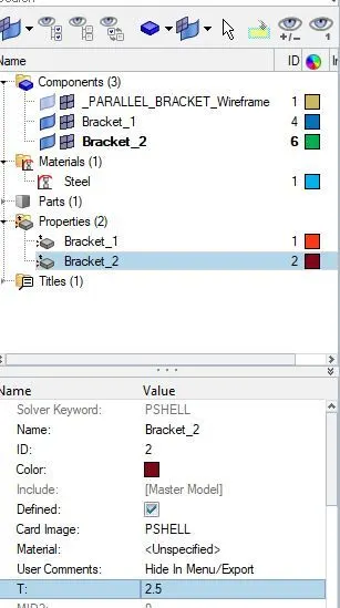
- Next, the material is defined as steel and the properties for both the surfaces are created with card image as ‘PSHELL’. One surface is assigned with thickness 2mm and the other 2.5mm. Also, assign the surfaces with material and their respective properties.
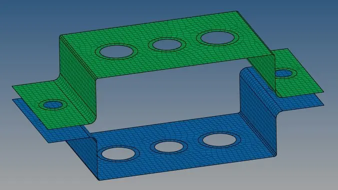
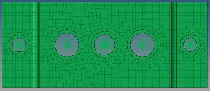
- Add washer split to all the holes and mesh both the surfaces, with the given element size, by selecting ‘automesh’ from “2D” menu.
- Create rbe2 link, with translational DOF constrained, in holes at ‘a’ by selecting ‘rigid’ in “1D” menu. Then construct a rbe3 link, with all DOF constrained, in holes at ‘b’ by choosing ‘ rbe3’ also from”1D” menu. After that, create another rbe3 link, with constrain only on x and y DOFs, I holes at ‘c’ and also make rbe2 link in holes at both ‘d’ and ‘e’.
- To create the cross- section of each components ‘HyperBeam’ option is used as following and assign the given respective dimensions.
Rod (Cross-Section: BOX) – HyperBeam + standard section + (HYPERBEAM + thinwalled box)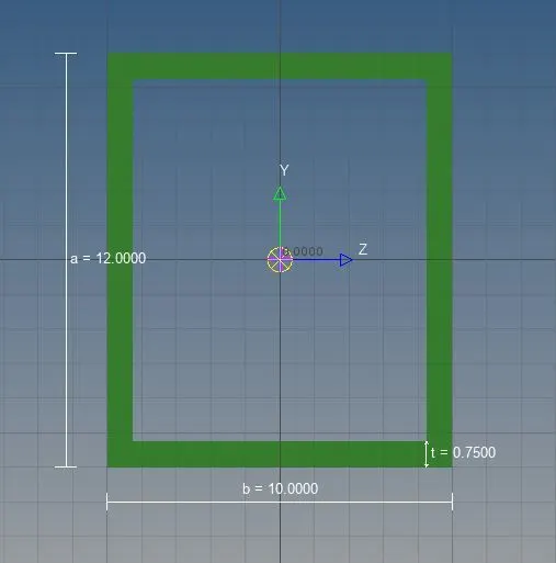
Beam (Cross-Section: I Section) - HyperBeam + standard section + (HYPERBEAM + standard I section)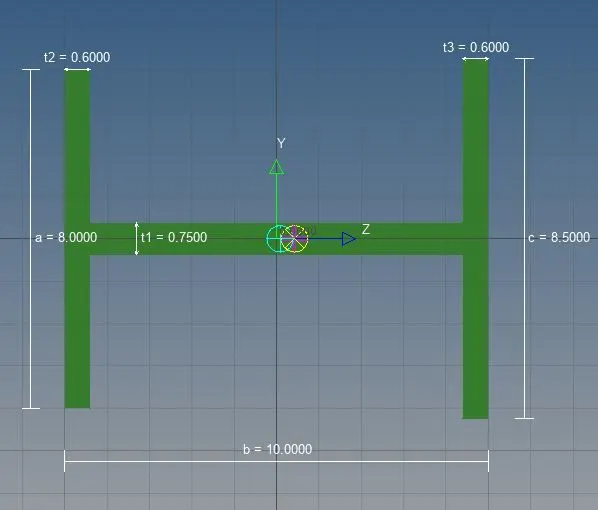
Bar (Cross-section: X section) -, HyperBeam + standard section + (OPTISTUCT + Cross)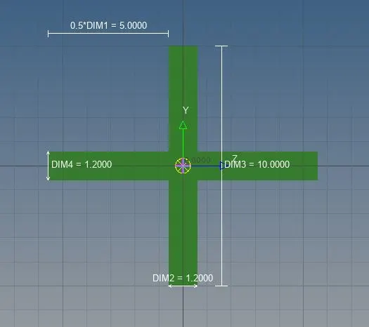
Also rename them as ‘Rod, ’Beam’ and ‘Bar’. - Now open ‘rod’ and select ‘CROD’ in ‘element type’ to create a rod at ’a’.Open ‘bar’ and select ‘CBAR’ in ‘element type’ to create a bar and select ‘CBEAM’ to make a beam.
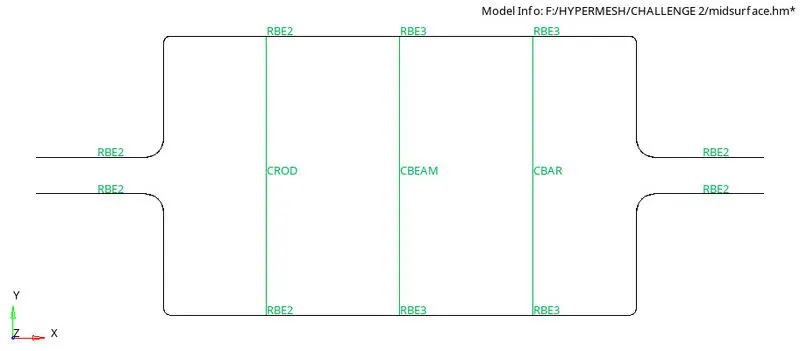
- Now add properties named ‘Rod, ’Beam’ and ‘Bar’. Then,
For rod, card image is given ‘PROD’ and beam section is assigned ‘Rod’.
For beam, card image is given ‘PBEAM’ and beam section is assigned ‘Beam’.
For bar, card image is given ‘PBAR’ and beam section is assigned ‘Bar’.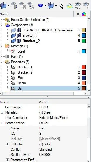
- Next , go to ‘rod’ in “1D” menu, then open ‘update’ and select ‘Bar’ in property to update the cross-section of rod. Similarly, both the cross- section of beam and bar are updated. Select “1D Detailed Element Representation” to get the 3D views of the components.
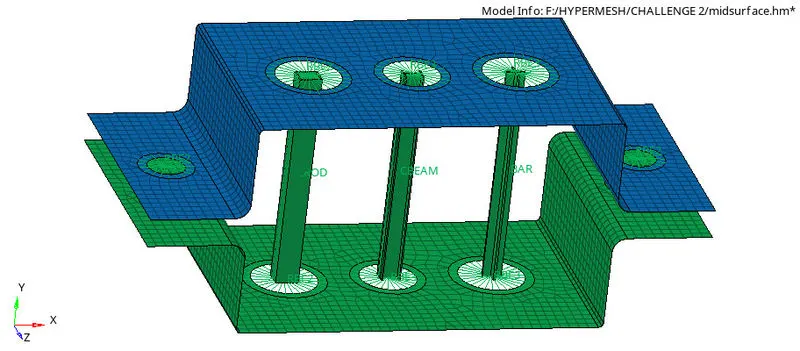
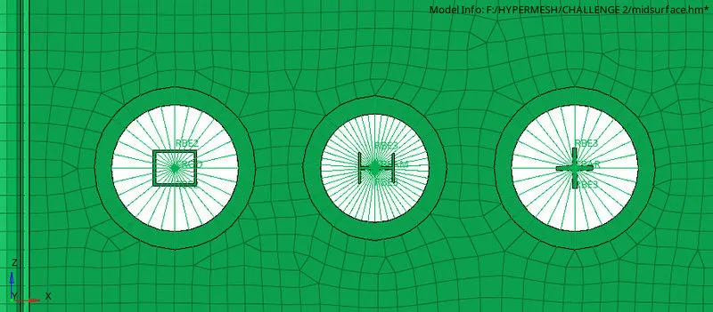
- Select ‘masses’ and assign mass of magnitude 10 at both the rbe2 links in holes ‘d’ and ‘e’
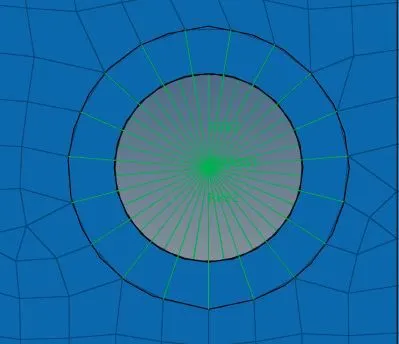
- Also create springs at both the end positions ‘f’ using the ‘springs’ option.
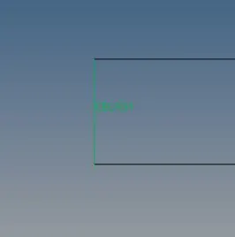
- Select “2D Detailed Element Representation” to represent the thickness in the view.
RESULT:
The following are the results obtained.
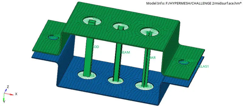
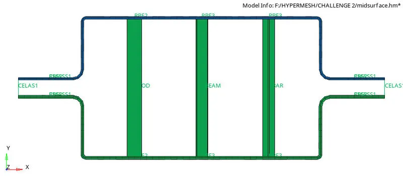
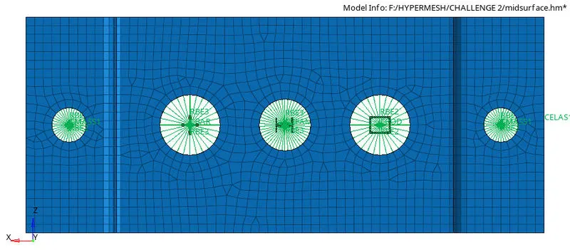
CONCLUSION:
- The mid surface I created successfully to avoid storage space of node and element by meshing in 3D.
- The 2D mesh was successfully generated over the mid surface obtained from the siolid component.
- The 1D element of the components which are characterised by different cross-section and parameter are also constructed.