Week 4-1D Element Creation Challenge
Objective:
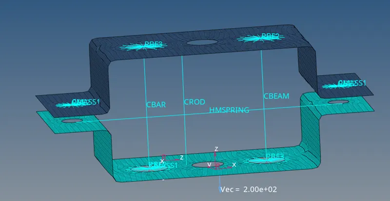
Mesh the Given component with the Size of 5 Units. Create 1D elements on the following component with given cross-section and DOF
a. Rod element:- Translational DOF should be Constrained with RBE2 link
Cross-Section: BOX- Dimension a= 12 mm
dimension b=10 mm
Thickness t= 0.75 mm
b. Beam element:- All DOF should be constrained with RBE3 link
Cross-Section: I Section- Dimension a= 8 mm
Dimension b= 10 mm
Dimension c= 8.5 mm
Thickness t1= 0.75 mm
Thickness t2= .6 mm
Thickness t3= .6 mm
c. Bar element:- Constrain only x and y DOFs With RBE3 link
Cross-section: X section- Dimension DIM1= 5 mm
Thickness DIM2= 1.2 mm
Dimension DIM3= 10 mm
Thickness DIM4= 1.2mm
d. & e. Apply the mass of magnitude 10 with the RBE2 link
f. Join the two components with Spring elements
Procedure:
- Import model
File>>Import>>Import Geometry
Select file and click import
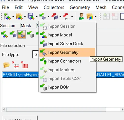
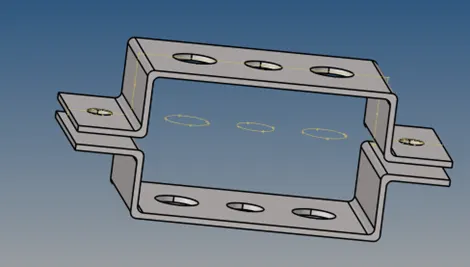
Go to Geometry>> Mid Surface>>Select a surface>>Click Extract
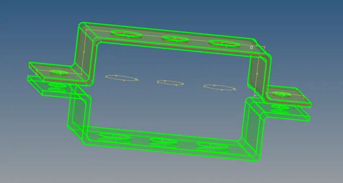
Extract the mid surface for both the surfaces.
Then, delete the solid surfaces using Delete>>Solid>>All
Change the colour of both middle surfaces.
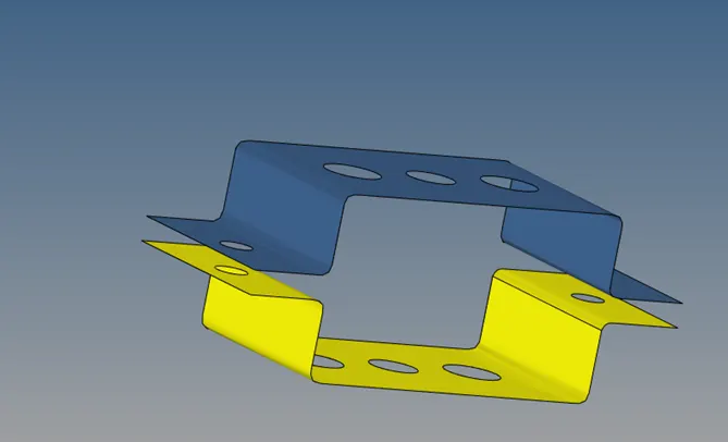
We can create a new component and move the existed component to new one using following method
Create a new component>>rename it>
Go to tool>>organise>>select the new surface>>choose the surface to move>>click on move
Now Assign material to component
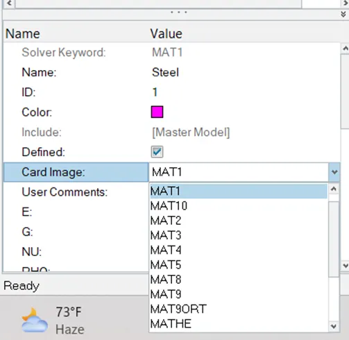
In the model section, go to material and right click>>create>>write material name
Select appropriate card image for material. Different companies specifies card image for different material.
Here we use card image MAT1 for steel material.
Now create two different property for different brackets
Go to Model>>Property>>right click>>create>>give property name
Now Assign Material and thickness to these properties. Make sure that Card image should be PSHELL
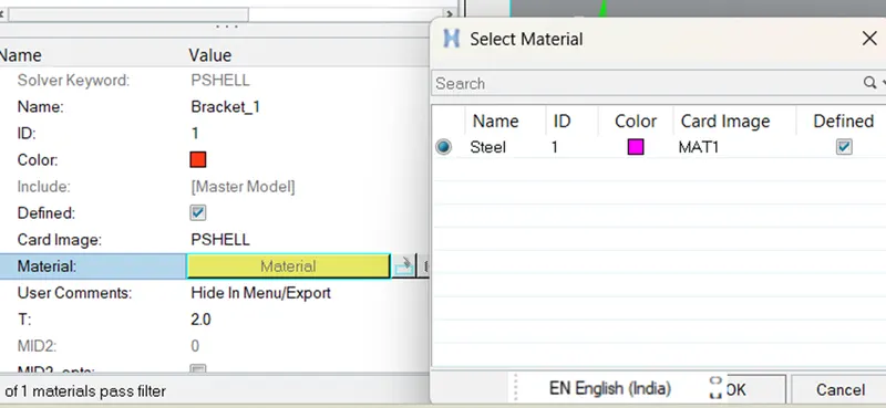
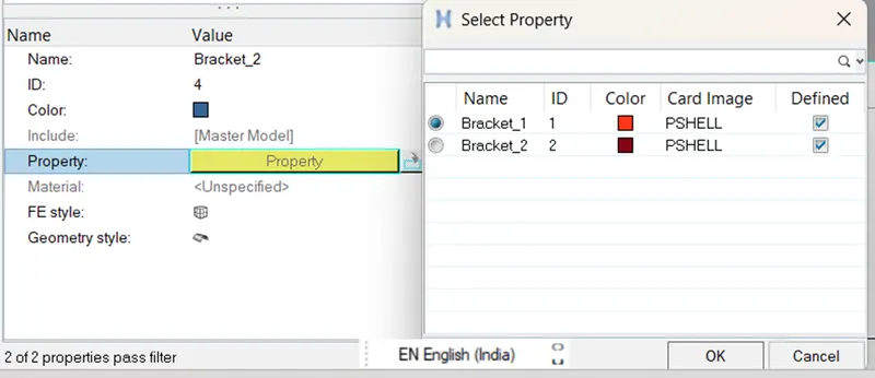
Now assign the property and material to components
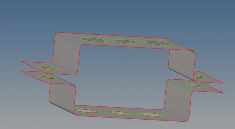
Now give washer splits of 5 mm to the holes
Go to Geometry>>Quick Edit>>Washer splits>>provide offset value and then select circles.
Now we will go for mesh
Go to 2D>>AutoMesh>>Select surface>>Select mesh type as Mixed>> element size = 5 >>Click on Mesh
We can change element size by putting different value and clicking on recalc all
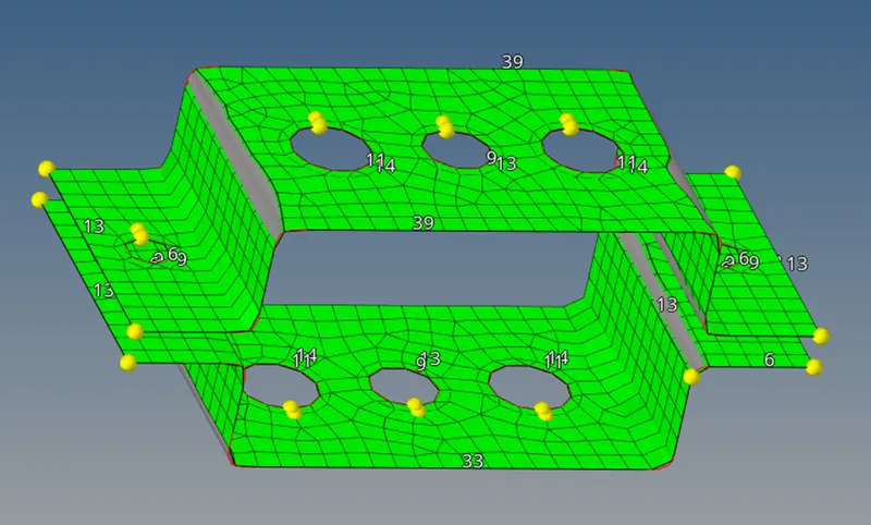
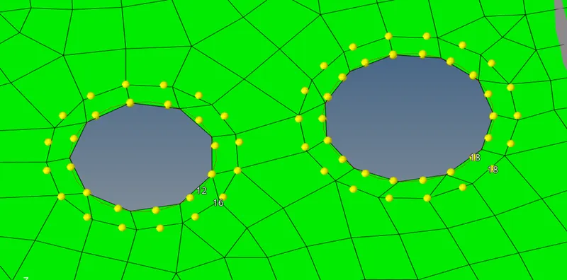
At washer zone we equate the number of nodes for proper mesh flow
Now click on return.
Creating RBE2 Node
Goto 1D>>rigids>>Select nodes>>Click on create (This is for one node)
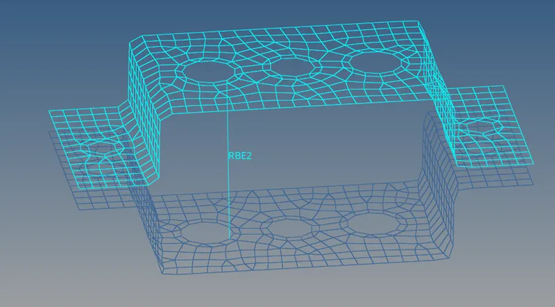
For multiple node
Select multiple node in dependent and calculate node in independent
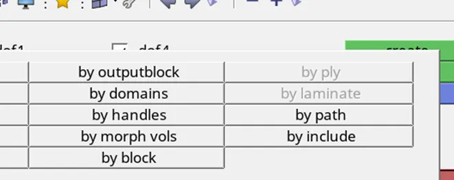
Choose nodes by path
Select nodes bye path as shown below and then click create. This is called RBE2 link not element because it is cluster of elements.
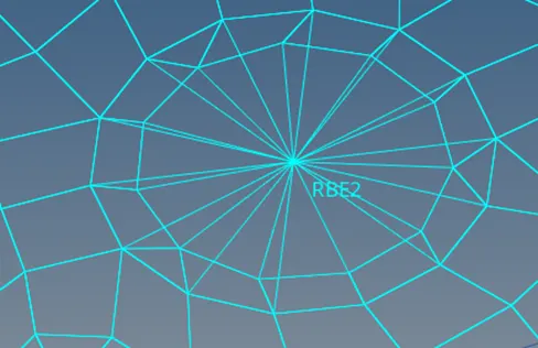
Now create RBE3 element
Goto 1D>>RBE3>>select nodes>>Click on create
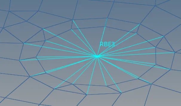
Putting mass on Nodes
Go to 1D>>masses>>create>>select node, mass, property, element type>>click on create

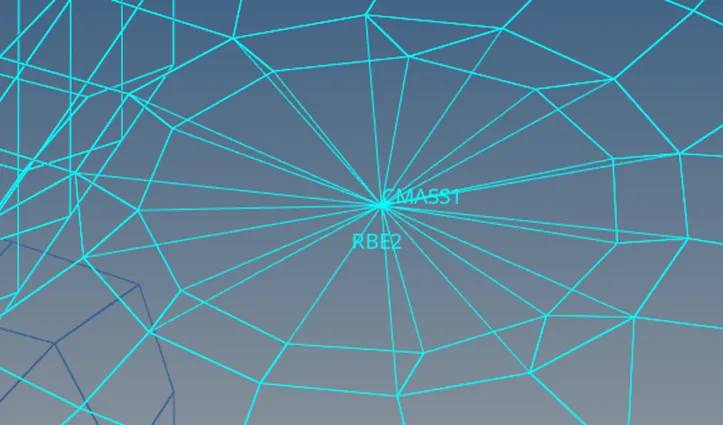
Now create beam cross section
Go to 1D>>hyperbeam>>standard section>>select hyperbeam as section and solid circle as section type>>click on create

A window will be pop out
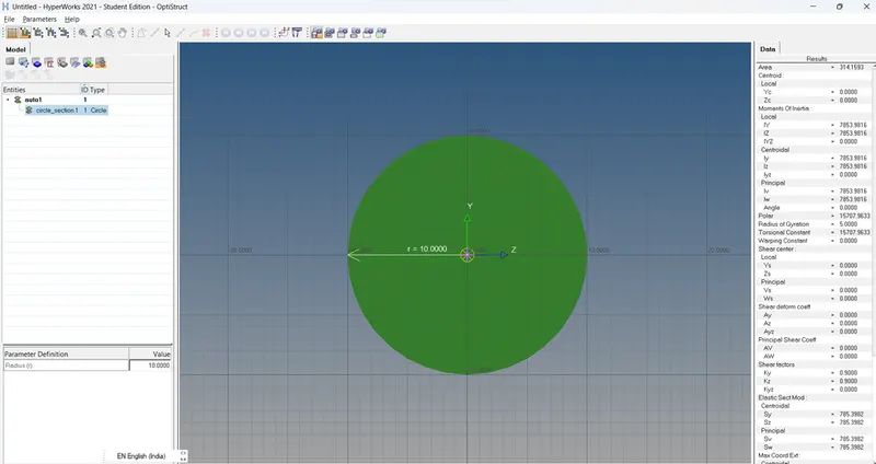
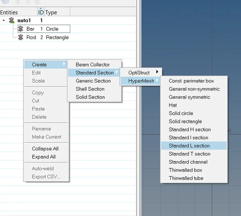
Right click>>create>>Standard Section>>Hypermesh>>
To create different sections
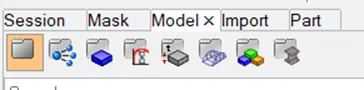
To go to hyperbeam view, goto model>>hyperbeamview
Now create Bar, Rod and Beam Element
Bar
1D>>Bar>>Bar2>>Select nodes>>Choose ‘CBAR’ as element types>>give orientation
Rod
1D>>Rod>>Create>>Select nodes>>choose ‘CROD’ as element types
Beam
1D>>Bar>>Bar2>>Select nodes>>Choose ‘CBEAM’ as element types>>give orientation
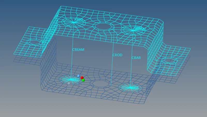
Create different property for Bar, Rod and Beam
Assign Card Image and Beam Section according to element
|
Rod |
Bar |
Beam |
|
|
Card Image |
PROD |
PBAR |
PBEAM |
|
Beam Sectiomn |
Rod |
Bar |
L_Section |
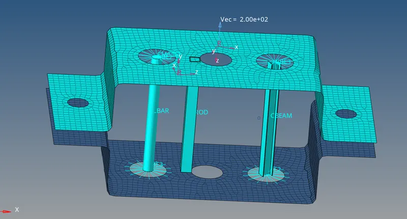
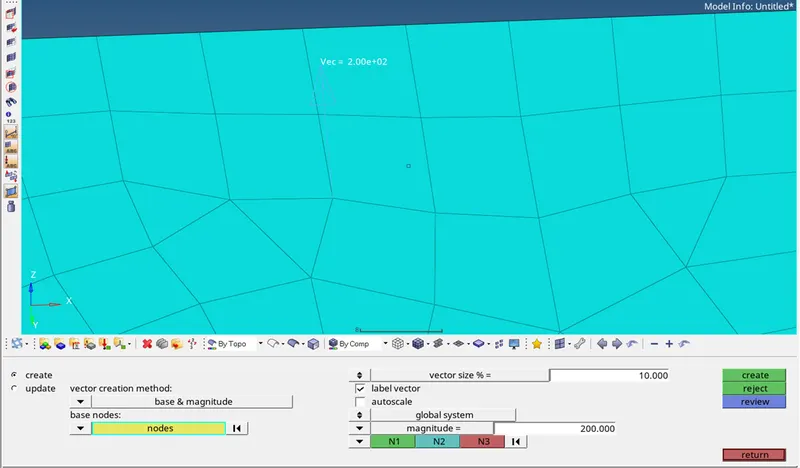
Create Vector
1D>>Vector>>Create>>provide vector size and magnitude>>Click on Create
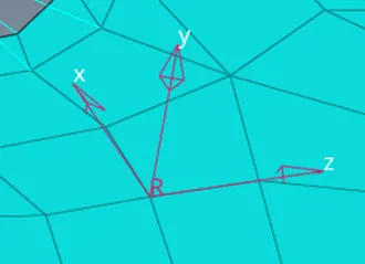
Co – ordinate System
Can be created by axis direction and node reference
1D>>systems>>create by axis direction>>Selects nodes>>select x-axis and xy plane>> create
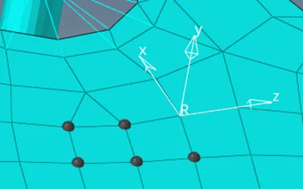
Assign nodes to system
1D>>Sysytems>>assign>>Select Nodes>>select co-oridnate system>>click on set reference
Add spring element
1D>>springs>>Select nodes
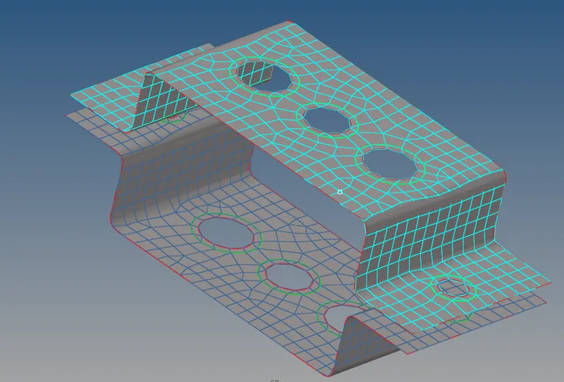
2D detailed element representation is as shown below
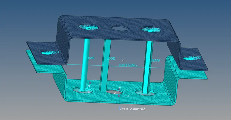
Conclusion: Thus, we have created the given model.