Week 4-1D Element Creation Challenge
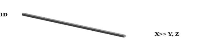
1D analysis refers to the application of finite element analysis (FEA) on line elements, i.e. 1-dimensional models comprised of only 2 nodes. 1D analysis can be applied to 2D and 3D models by analyzing the individual line elements that form the models' finite element mesh.
Procedure :
Import the model by using geometry option in the form of IGES format
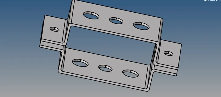
As the thickness of the given component is uniform, the midsurface is taken for the whole model.
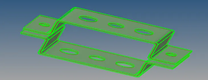
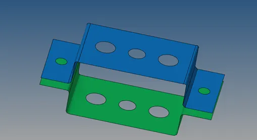
Create Bracket_2 and Create Bracket_1
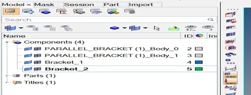
Delete the solids surface and delet the parallel Bracket_1 and Bracket_2
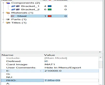
I have assigned this material now let me assign a property to that particular material.
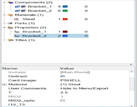
And let me, create another property which is for bracket, two so why am I creating two properties because I am going to give two thickness in these two properties two different.
Different different thicknes this.
One and let me create another property.
Then we assign the material & properties to the midsurface component in the model browser.
material
Properties
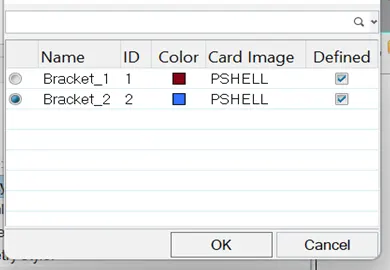
Now, assign the same thing to the , componrnt as well so now click on the component it will show material as a property so just have to mention the property and it will automatically assign the material.
Same here Bracket_1 and Bracket_2
Now, if we do 2D mesh here, let’s perform a 2D mesh, which is basically auto mesh,
Once materials & properties are assigned, we are meshing the component, by using automesh option in 2D & target element length should be 7 mm Then we create washer split surface for the holes.
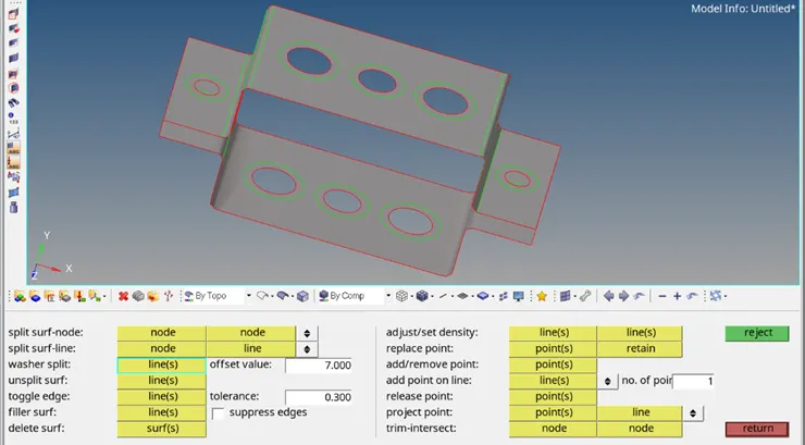
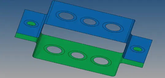
Let’s Do the 2D mesh. Let’s click all the surface which are displayed and now.
Click on mesh.
So element size is
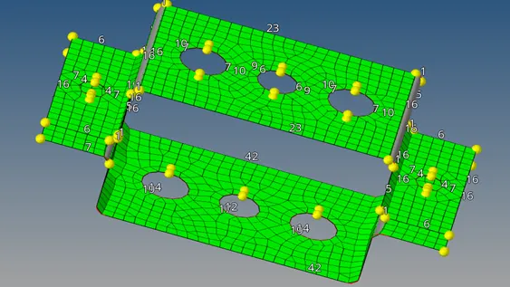
This is basically by right-clicking to increase the amount of nodes there and by left – clicking the decrease the amount of nodes.
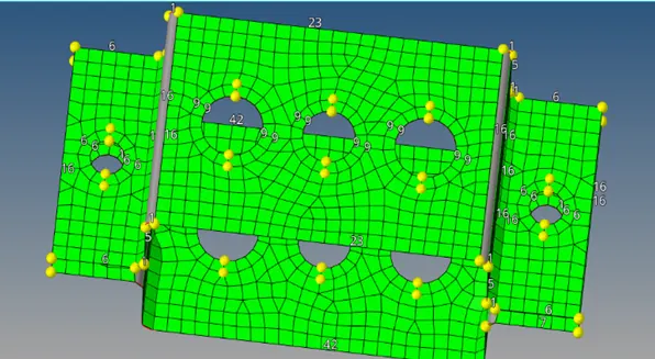
So we are not worried about the quality of the mesh right now.
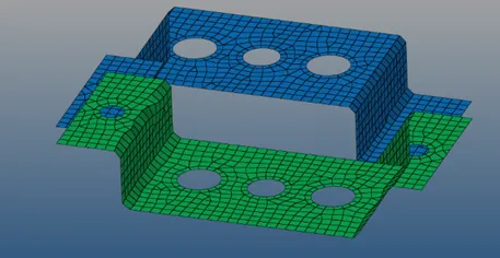
We create RBE2 elements using rigids in 1D module for the first holes in top & bottom & we restrict the element to transitional DOF in X,Y & Z axis as mentioned for the first case.
Rigid element are basically RBE 2 elements which have infinite stiffness. Infinite stiffness it, means it will never bend it never rotate it will never move from the particular node. Actually just move the node here and there that it the entire element .
When RBE 3 elements this has a different property its actually can be moved left right up down move forward and backward and the lower distribution is also, pretty different how the RBE2 element actually distributes the load .
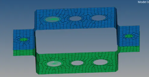
What is the major difference between RBE3 will RBW2 elements our links basic layers, RBE will distribute the load equally to each and every element irrespective of their position irrespective of their distance from the independent node,
And RBE 3 the lower distribution is different and its not exactly uniform lets say if there is an element close by which is this which will have more load to distributed ti, it then element which is a little farther away .
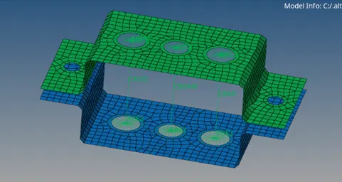
Then we create cross sections for Rod, Bar & Beam
We create cross sections for the rod in the form of thin wall box which has been given for the first case.
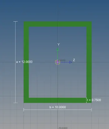
We create cross section for the beam in the form of I-section which has been given for the second case.
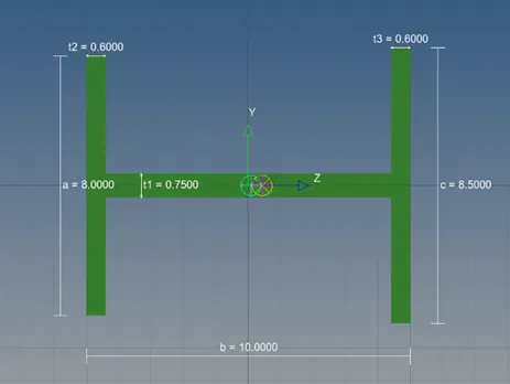
We create cross sections for the bar in the form of Cross-section which has been given for the third case.
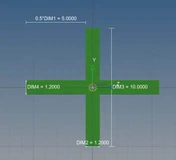
Once cross sections are created, we need to create property for Rod, Beam, Bar with property cards such as PROD, PBEAM, PBAR
Mass is applied with the magnitude of 10 in RBE2 & spring elements are joined as been mentioned.
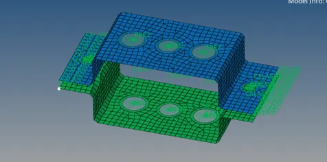
Join the two components with spring elements.