Week 4-1D Element Creation Challenge
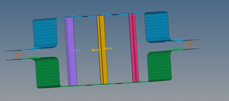
Objective: To mesh the given component with element size of 5 Units. Further create 1D elements on the following component with given cross- section and DOF
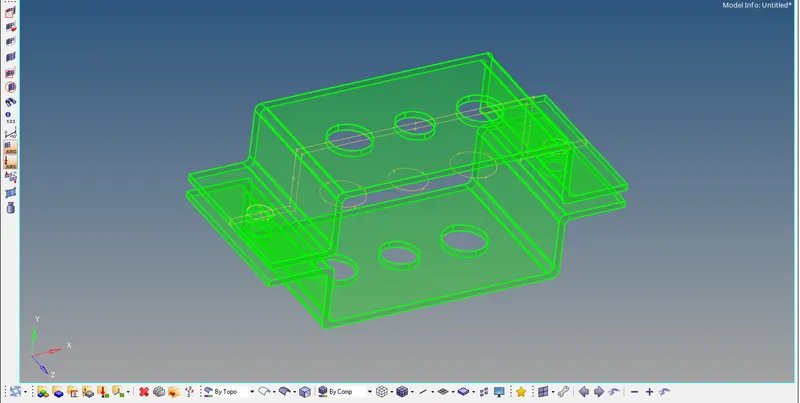
CAD Model: IGES file
Procedure:
- Importing the Model
- Open the Hyperworks Desktop - 2022 Student Version.
- Then Click on Import Solver deck icon
 present on the top toolbar.
 - Click on Import Geometry icon
 from the list of options. Select the File type from the dropdown as IGES. The files will be either listed below or click on the File icon below to load the CAD model from the desired destination folder of the computer.
 - Finally cllick on Import. The model gets loaded into the workspace.
2. Extracting the mid-surface of the upper bracket component
- Firstly, we will start by disabling the lower bracket part present on the workspace by clicking on the Geometry
 under the Components feature tree.
 - Change the Geometry color model to "By Topo"
 and click on bulllet next to Geometry and click on midsurface.

- In the Autoextraction option, we click on the arrow next to the surfs and selected displayed to completely select the upper bracket solid.


- From the extraction options, for our convenience, we select skin offset option from the dropdown. Finally we click on the extract option.

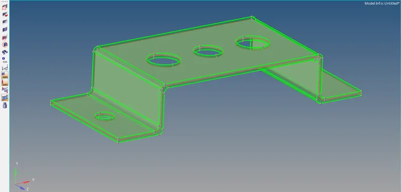
(The midsurface is extracted as indicated by the red edges in between the green edges.)
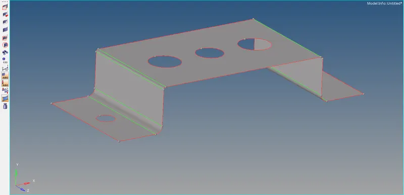
Midsurface extracted from the Upper bracket
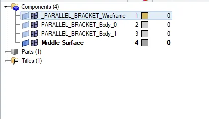
- We rename the Middle surface generated under the components tree to "Upper_Bracket_Surface"
3. Meshing separately the upper and lower brackets
- Before start of the mesh, we do preliminary checks of the generated middle surface. One such check is done on the surface near the created holes, as the geometry of the holes will not be captured properly once it is automeshed, therefore some operations need to be done.
- For this we go to quick edit present under the Geomety and click on washer-split. Next to it we click on the line(s) option and choose the lines which represents the geometry of the different holes created.
- We will set the offet value to 5mm which is the size of the element to be used for meshing. and click on the workspace. The required changes are made and further clicked on return.
- Next, from the bottom toolbar click on bullet next to 2D and further click on Automesh option. Alternatively one can press F12 from the keyboard. This opens the automesh option directly.

- From the surfs option click on Displayed. This will select the displayed surface present on the workspace and refrain from selecting other geometry wich are still disabled on the workspace. Input the element size as 5mm and mesh type as mixed.
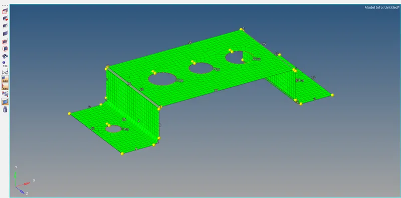
- Further click on Mesh. The entire surface gets meshed. Click on the mouse wheel button to accept the mesh or click on return to accept the mesh.
4. Extracting the mid-surface of the lower bracket component
- Firstly, we will start by disabling the upper bracket mid surface present on the workspace by clicking on the Geometry and element
 under the Components feature tree and enable the lower bracket solid part.
 - Under the components tree, we right click and after that a dropdown appears, we click on create to expand to a new component and rename as "Lower_Bracket_Surface".
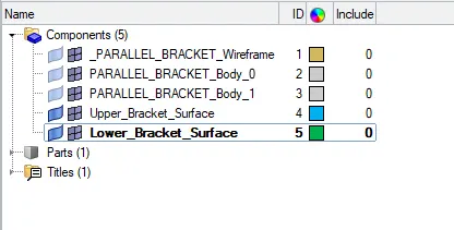
We repeat the EXACT PROCEDURE as done for extracting the midsurface of the upper bracket component and get the final mid surface as shown below:
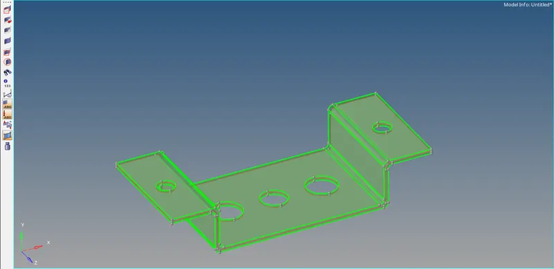
(The midsurface is extracted as indicated by the red edges in between the green edges.)
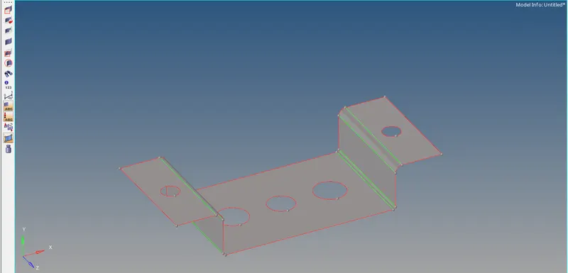
Midsurface extracted from the Lower bracket
- Now the created middle surface has to be connected to the "Lower_Bracket_Surface" component wich was created. For this, we click on the bullet next to the Tool and choose organize.


- From the first drop down arrow next to elems, we replace it by clicking on Surfs and further clicking on Surfs, select on Displayed. This will select the complete surface present in the Workspace. Observe the dest component = Lower_Bracket_Surface
- We click on Move and the properties are transferred to the Lower_Bracket_Surface component. Further delete the middle surface component generated.
5. Meshing the lower bracket
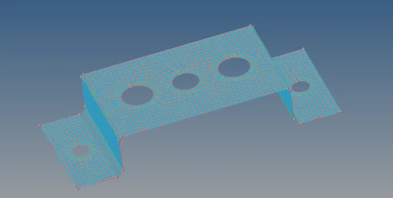
We repeat the EXACT PROCEDURE as done for meshing the midsurface of the upper bracket component and get the mesh as shown below:
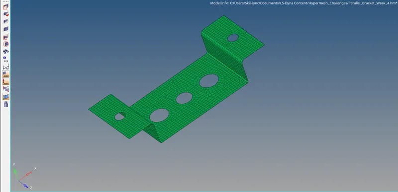
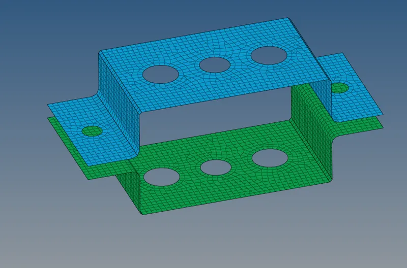
The final mesh of the complete bracket is shown below:
-----------------------------------------------------------------------------------------------------------------------------
Creating the following 1D elements on the parallel brackets
a. Rod element:- Translational DOF should be Constrained with RBE2 link
Cross-Section: BOX- Dimension a= 12 mm
dimension b=10 mm
Thickness t= 0.75 mm
- Creating RBE2 link
Click on the 1D option in the bottom toolbar and select rigids from the Second column. These rigids essentially are the RBE2 elements with infiite stiffness. We click on that.

Click on the drop down next to the node and select calculate node. Further, below it, click on the node below to select the inner and the immediate nodes which surrounds the hole on the component by path.
Check in the translational degree of freedom as dof1, dof2 and dof3. Finally click on create. The created nodes create a node at the center which is based on the mass center of the selected nodes.


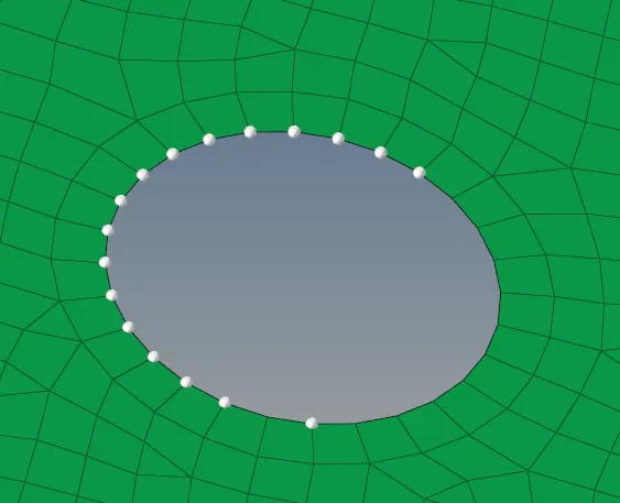
Similar procedure was followed for creating RBE2 link for the bottom bracket.
- Generating a rod element
- Before generating the rod element, we start by defining the cross-section of the rod. For this click on the 1D option in the bottom toolbar and select Hyper Beam from the third column.

- Choose Standard section from the list of options. From the standard section library choose HYPERBEAM and standard section type choose thinwalled box.

- Finally click on create. This opens a new window to define the dimension of the thinwalled box. Define all the dimension as given in the question and rename the section to Rod_box_Section.
- Click on model view icon  present on the top left corner of the window to return to the Hypermesh screen.
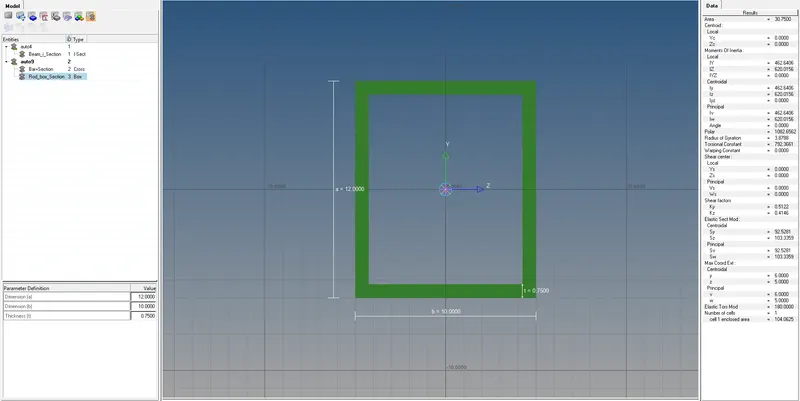
- Under the component tree, create a new component and rename as "Rod-box-Section". Further make this newly created blank component as the current coponent.
- Under the property tree, create a new property for the beam and rename as "Rod_Property". Click on it after creation.
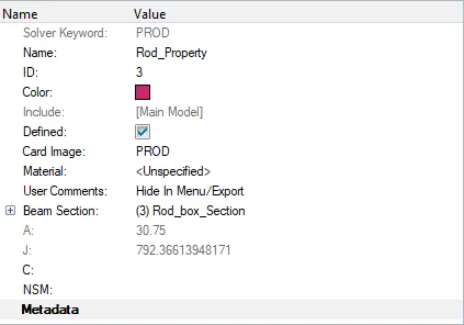
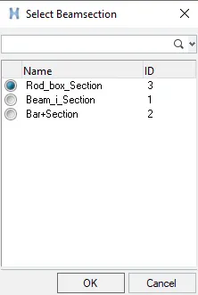
- Change the card image to the PROD by clicking on it and selecting PROD from the dropdown and update the Beam Section by clicking on it and updating it to already created Rod_box_Section in the Hyperbeam.
- Finally click on the component "Rod-box-Section" and update the property to Rod_Property.
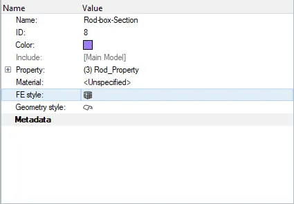
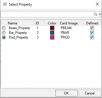
- Click on the 1D option in the bottom toolbar and select rods from the Second column.

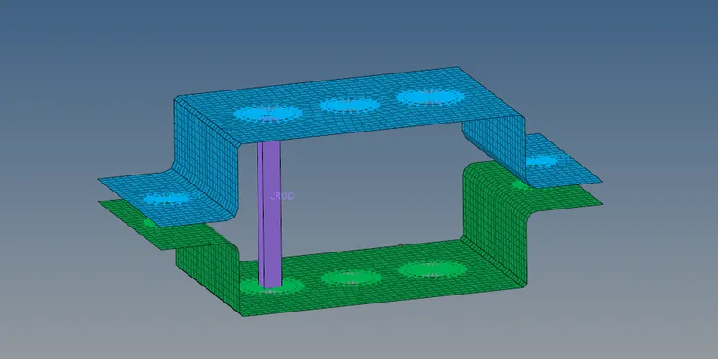
- Choose two central nodes from the created RBE2 links on the upper and lower brackets. Update the property = ''Rod_Property" and elem types =CROD.
- To view the created beam element along with the developed cross section, click on drop down arrow next to  icon and choose 1D Detailed Element Representation.
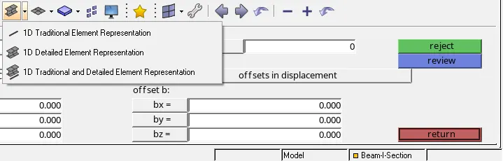
- The rod element gets represented as
-----------------------------------------------------------------------------------------------------------------------------
b. Beam element:- All DOF should be constrained with RBE3 link
Cross-Section: I Section- Dimension a= 8 mm
Dimension b= 10 mm
Dimension c= 8.5 mm
Thickness t1= 0.75 mm
Thickness t2= .6 mm
Thickness t3= .6 mm
- Creating RBE3 link
Click on the 1D option in the bottom toolbar and select rbe3 from the Second column.
Creation of RBE3 links for both the brackets in this case is followed by the same procedure above as in case of RBE2 links. Here all the DOF's are constrained.
- Generating a beam element
- Before generating the beam element, we start by defining the cross-section of the beam. For this click on the 1D option in the bottom toolbar and select Hyper Beam from the third column.
- Choose Standard section from the list of options. From the standard section library choose HYPERBEAM and standard section type choose Standard I Section.
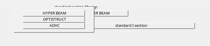

- Finally click on create. This opens a new window to define the dimension of the I-section. Define all the dimension as given in the question and rename the section to Beam_i_Section.
- Click on model view icon present on the top left corner of the window to return to the Hypermesh screen.
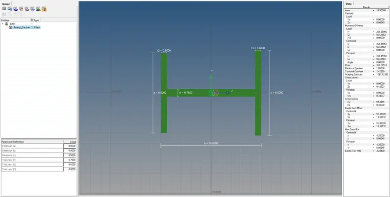
- Under the component tree, create a new component and rename as "Beam-I-Section". Further make this newly created blank component as the current coponent.
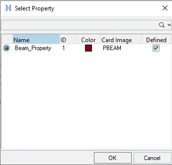
- Under the property tree, create a new property for the beam and rename as "Beam_Property". Click on it after creation.
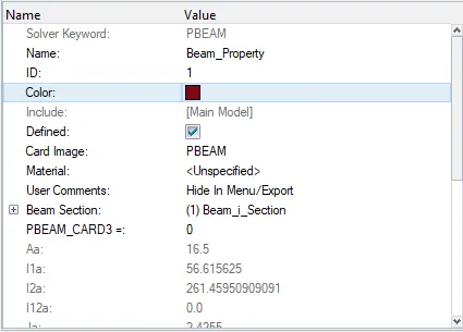
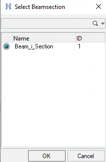
- Change the card image to the PBEAM by clicking on it and selecting PBEAM from the dropdown and update the Beam Section by clicking on it and updating it to already created Beam_i_Section in the Hyperbeam.
- Finally click on the component "Beam-I-Section" and update the property to Beam_Property.
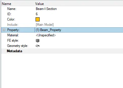
- Click on the 1D option in the bottom toolbar and select bars from the Second column.
- Select the node A as the center node of the created first RBE3 link at the second hole of the upper bracket and node B as the center node of the RBE3 link at the lower bracket.
- Choose N1 and N2 as nodes to indicate the position for cross section of the beam and finally hit on Tab to create the beam. Update the property = ''Beam_Property" and elem types =CBEAM. Keep all the other parameters as default.


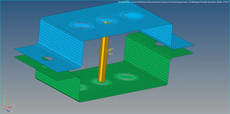
- To view the created beam element along with the developed cross section, click on drop down arrow next to icon and choose 1D Detailed Element Representation.
- The beam element gets represented as
-----------------------------------------------------------------------------------------------------------------------------
c. Bar element:- Constrain only x and y DOFs With RBE3 link
Cross-section: X section- Dimension DIM1= 5 mm
Thickness DIM2= 1.2 mm
Dimension DIM3= 10 mm
Thickness DIM4= 1.2mm
-
- Creating RBE3 link
Creation of RBE3 links for both the brackets in this case is followed by the same procedure above as in case of RBE2 links. Here only x and y DOF's are constrained.
- Generating a bar element
- Before generating the bar element, we start by defining the cross-section of the bar. For this click on the 1D option in the bottom toolbar and select Hyper Beam from the third column.
- Choose Standard section from the list of options. From the standard section library choose OPTISTRUCT and standard section type choose Cross.
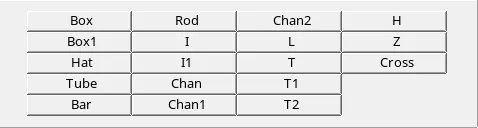
- Finally click on create. This opens a new window to define the dimension of the plus (+) section. Define all the dimension as given in the question and rename the section to Bar+Section.
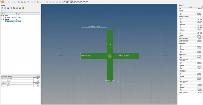
- Click on model view icon present on the top left corner of the window to return to the Hypermesh screen.
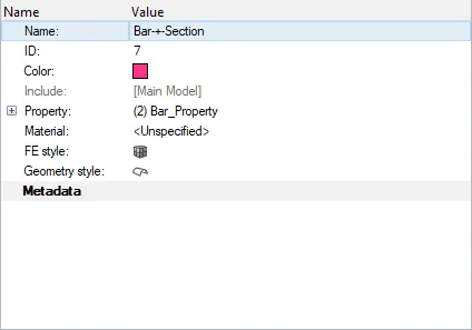
- Under the component tree, create a new component and rename as "Bar-+-Section". Further make this newly created blank component as the current coponent.
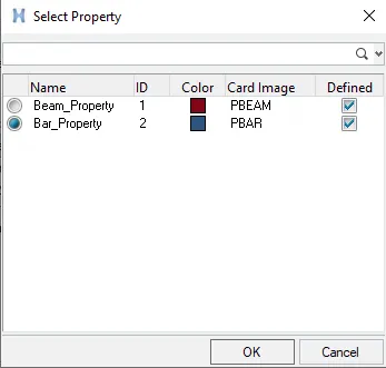
- Under the property tree, create a new property for the beam and rename as "Bar_Property". Click on it after creation.
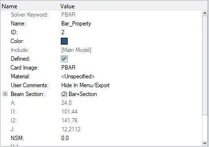
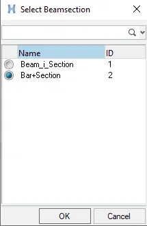
- Change the card image to the PBAR by clicking on it and selecting PBAR from the dropdown and update the Beam Section by clicking on it and updating it to already created Bar+Section in the Hyperbeam.
- Finally click on the component "Bar-+-Section" and update the property to Bar_Property.
- Click on the 1D option in the bottom toolbar and select bars from the Second column.
- Select the node A as the center node of the created second RBE3 link at the third hole of the upper bracket and node B as the center node of the RBE3 link at the lower bracket.
- Choose N1 and N2 as nodes to indicate the position for cross section of the bar and finally hit on Tab to create the bar. Update the property = ''Bar_Property" and elem types =CBAR. Keep all the other parameters as default.
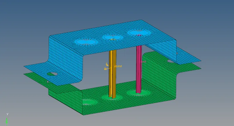
- To view the created bar element along with the developed cross section, click on drop down arrow next to icon and choose 1D Detailed Element Representation.
- The bar element gets represented as
-----------------------------------------------------------------------------------------------------------------------------
d. & e. Apply the mass of magnitude 10 with the RBE2 link
- Create RBE2 link
Creation of RBE2 links for both the brackets in this case is followed by the same procedure above in case of (a).
- Applying the mass
Click on the 1D option in the bottom toolbar and select masses from the first column.
Select the created centre node from RBE2 link and add mass=10. Choose elem types = CMASS1 (for instance). Finally click on create.

Repeat the above step for the RBE2 link created on the hole at the other end of the upper bracket as well as the two end holes of the lower bracket.
-----------------------------------------------------------------------------------------------------------------------------
f. Join the two components with Spring elements
- Under the component tree, create a new component and rename as "Springs". Further make this newly created blank component as the current coponent.
- Click on the 1D option in the bottom toolbar and select springs from the second column.

- Select a node on the width of one of the end of both the two brackets. Set any dof (dof2 for instance) for the spring element and elem types = CELAS1.
- The spring element gets represented as