Week 4-1D Element Creation Challenge
AIM - To mesh the given bracket and create 1D elements.
OBJECTIVE:
- To extract the midsurface of the given bracket and mesh it.
- To create Rod elements with given cross section and degree of freedom.
- To create Beam elements with given cross section and degree of freedom.
- To create Bar elements with given cross section and degree of freedom.
- To create RBE2 (rigids) link and RBE3 link in the specified places of the bracket.
- To add mass of magnitude 10 to RBE2 link at specified place of the bracket.
- To Join the two components with spring elements.
PROCEDURE:
- At first midsurface was extracted for the brackets one by one and named in component list as Bracket 1 and bracket 2.
- After that wsher split was added near the whole region.
- Then the componets were meshed.
- After that Rigid RBE2 link was created at postion a, d and e and the degree of freedom was contraint as specified.
1D element → rigid → nodes slection → DOF selection → create
- After creating RBE2 links RBE3 links were created for position b and c and the degree of freedom was contraint as specified.
1D element → RBE3 → nodes slection → DOF selection → create
- Then create CRod, CBeam and CBar by connecting the RBE2 links with RBE2 and RBE3 links with RBE3
1D element → bars → nodes slection → select elemnt types (as CBar then Cbeam) → Create.
1D element → Rods → nodes slection → select elemnt types (as CRod) → Create.
- Then went to Hyperbeam to create Box section, Isection and Cross section as per the given dimension.
- Then came back to model window from hyperbeam window and create material and property for Bracket 1, Bracket 2, Rod, Beam and Bar.
- Then assigned thickness and material to Bracket 1 and Bracket 2 in property. Assigned card image as PRod, PBeam and PBar to Rod, Beam and Bar in property. Assigned material and Beam section to Rod, Beam and Bar which was created in Hyperbeam.
- After that updated the 1 D elements that were created earleir with property and other factors. This step was done separtely for each 1 D elements.
1D element → bars → update → select property ( Bar and then Beam) →nodes slection → select elemnt types (as CBar then Cbeam) → Update.
1D element → Rods → update → select property (Rod) → nodes slection → select elemnt types (as CRod) → Update.
- Then click on Detail 1D Element Rpresentation. To see the sections that were created in Hyperbeam.
PROCEDURE IMAGE:
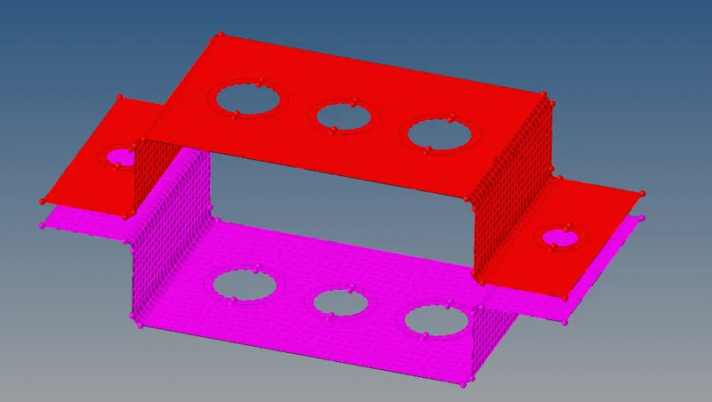
- The above image shows the mid surface of braket 1a nd 2 along with mesh.
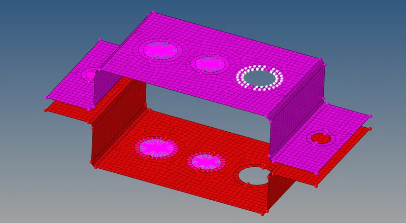
- The above image shows the RBE2 AND RBE3 links along with node selection that will help to create new RBE3 link.
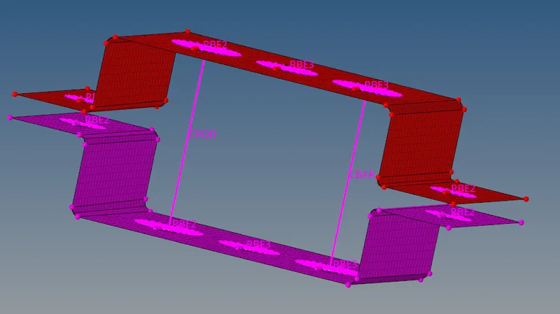
- The above image shows CROD and CBAR 1D elements that are created by connecting 2 RBE2 and RBE3 link.
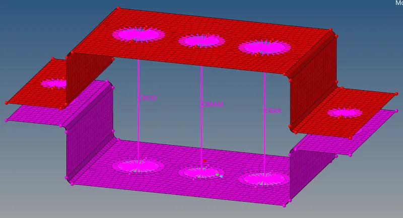
- The above image shows the 1D CBEAM element that is created by connecting 2 RBE3 link.
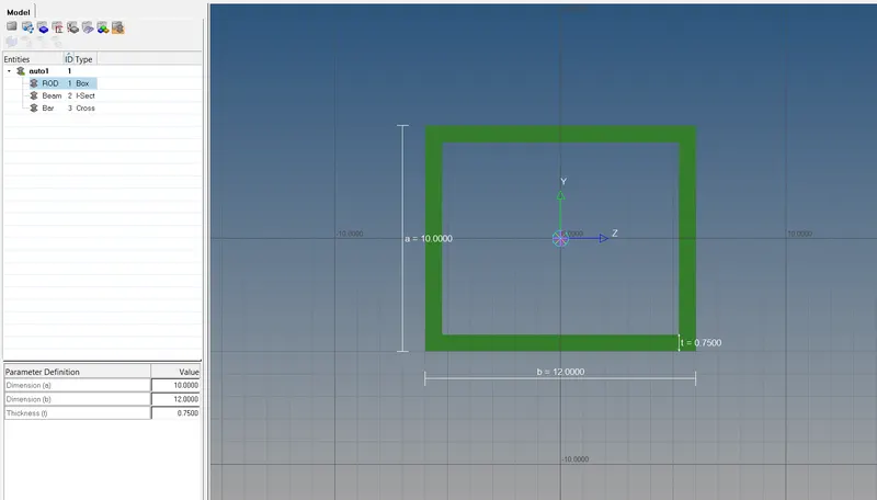
- The above image shows the Hyperbeam window where the Rod, Bar and Beam are created as per the given dimension.
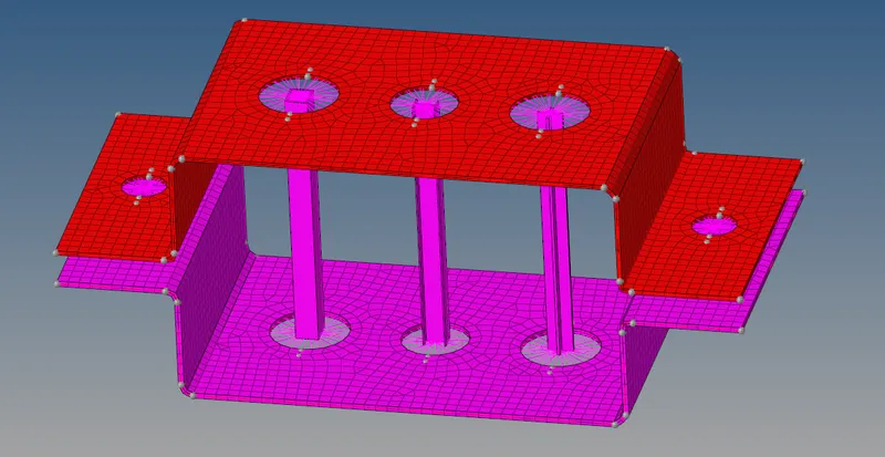
- The above image shows the Detail 1D representation of the the above process where we can observe the thickness in midsurface and the 1D elements.
OBSERVATION:
- Midsurface was extracted and mesh was done on the midsurface.
- 1D Elements were created.
CONCLUSION:
- Through this assignmnet 1D element creation concept was introduced and cleared.
- Learned to create RBE2 and RBE3 links and use Hperbeam.
- Learned to assigned material and property to 1D elements.