Week 4-1D Element Creation Challenge
Objective-
Mesh the Given component with the Size of 5 Units. Create 1D elements on the following component with given cross-section and DOF.
a. Rod element:- Translational DOF should be Constrained with RBE2 link
Cross-Section: BOX- Dimension a= 12 mm
dimension b=10 mm
Thickness t= 0.75 mm
b. Beam element:- All DOF should be constrained with RBE3 link
Cross-Section: I Section- Dimension a= 8 mm
Dimension b= 10 mm
Dimension c= 8.5 mm
Thickness t1= 0.75 mm
Thickness t2= .6 mm
Thickness t3= .6 mm
c. Bar element:- Constrain only x and y DOFs With RBE3 link
Cross-section: X section- Dimension DIM1= 5 mm
Thickness DIM2= 1.2 mm
Dimension DIM3= 10 mm
Thickness DIM4= 1.2mm
d. & e. Apply the mass of magnitude 10 with the RBE2 link
f. Join the two components with Spring elements
Procedure-
1.Import the given model in Hyperworks.
2. We need to acquire the midsurface first in order to generate mesh on it,so go to Geometry>Midsurface & select all the surfaces of which we need to extract the midsurface from.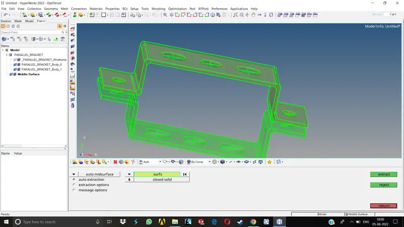
3.As this component consists of 2 separate parts, we will be having 2 separate midsurfaces.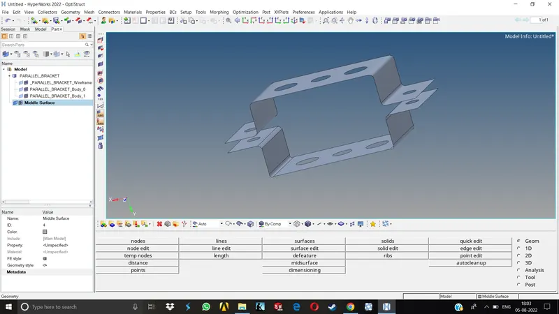
4.Now, the mid created will automatically be shown in the same component of the part.We will be assigning new component for each of these midsurfaces in order to assign proper thickness and materials later on. For doing hte same we need to Right click on the component and select Create.
5.The new components are named as MID1 & MID2. For moving the midsurfaces from the default component property to the new one we need to go to Tools>Organize , then it will be showing to us the association of the given part with respective component.
6.Once we make sure that the correct component is selected , we can then move the desired surfaces to the newly created components by Collectors>Surfaces>Select the desired surfaces>Move, Midsurfaces are now successfully moved to the new components.
7.Next step will be assigning proper material to the components. Right click anywhere on the blank area under Model tab as we did before for creating component, Create>Material, rename it as steel,as we are assuming this to be a steel component.
8.We need to create new properties in order to assign above materails to them.The procedure will be quite similar as above, Create>Property, here we have created them as Bracket1&2 resp. Now, go to these properties, on the bottom left area, we can see under Card image and Material it says Unspecified. Set the card image as PSHELL as this is a shell component, and select the material as steel.
As this process of assigning properties is done, we can now proceed to mesh the midsurfaces.
Meshing
1.Before meshing, we need to create washer splits around the holes.Go to Geometry>Quick Edit>Washer Spilts, Select the lines and give offset distance, here we have given the offset distance as 5 mm.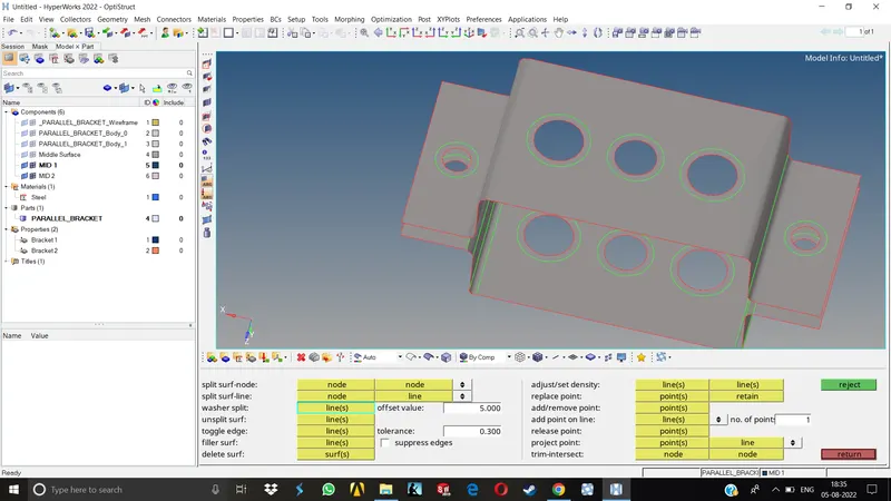
2.After creating the washer splits, go to 2D>Automesh, give the element size as 5 units and element type as mixed& select the surfaces we need to mesh. Click on mesh to complete the operation, the mesh is created now.
3.We can observe that the no. of nodes around the circle of washer spilts are non uniform,hence the mesh flow is kind of disturbed.We need to increase & decrease the no. of nodes around them in order to get them equal no. of nodes and then hit middle click, now the mesh will be a lot better.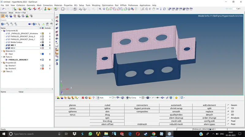
After meshing, we can now proceed with 1D element creation.
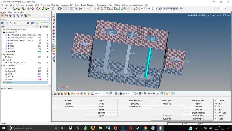
As mentioned in the objective, we need to create Rod,Beam,Bar & Spring elements. For doing so we first need to create RBE2 and RBE3 elements wherever necessary. We will create RBE2 cluster on the first hole in the middle section of the bracket,RBE3 on the second & third one, RBE2 on the holes located at both the ends of the bracket as specified .
1. GO to 1D>Rigids & select the nodes around the hole as well as the washer split by path. Click on create to complete the operation. The same way we can create RBE3 cluster wherever necessary.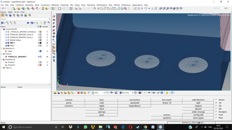
2.Once the clusters are created we can now create the ROD element by going to 1D>Rod>Create, now select the master nodes of the clusters and assign the element type as CROD, keep the property tab blank as we need to create those properties in the Hyperbeam with specified dimensions later on. Middle click will complete the operation and the nodes will be connected with a single line representing CROD.
3.Similar way we can create the Beam & Bar elements and leave the property blank.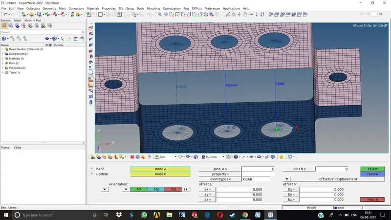
4.For the holes d&e, we need to apply a mass of magnitude 10 units. Go to 1D>Masses, specify the mass as 10 keep the element type as default and select the master nodes of the resp. RBE2 Clusters and on middle click, the magnitude will be applied on the nodes.
5.For the spring element at areas f, go to 1D>Springs>Create select the nodes on either end on the specified area one by one, keep the element type as CELAS1, dofs as default and hit middle click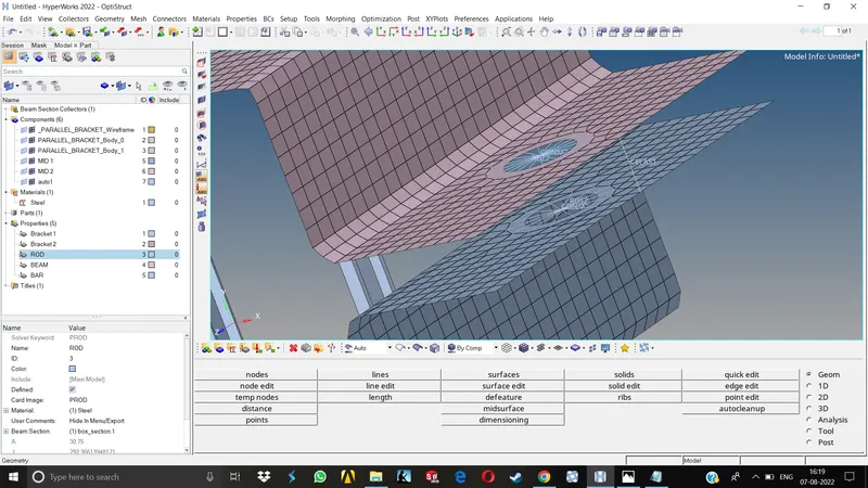
6.Now in order to create the Rod, Beam & Bar elements with their specific dimensions, we need to go to 1D>Hyperbeam. It will take us to another window.
7.In Hyperbeam Right click under the entities>Create>Std Section>Hypermesh & choose the desired std section type. Once we select the std section type , we can assign them desired dimensions under the parameter definition.Here we will be creating Rod, Beam & Bar elements acoording to their specified dimensions.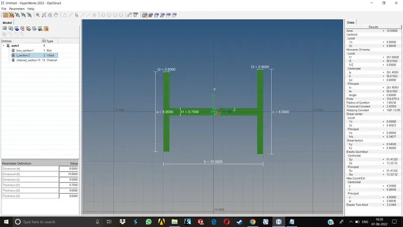
After creating these elements in hyperbeam we can get back to the hyperworks window by clicking on the Model view in the top left corner.
8.Now we need to assign properties for these Rod,Beam and Bar elements.Rght click under the model view anywhere in the blank space and Create>Property. Rename each of them as Rod,Beam & Bar. 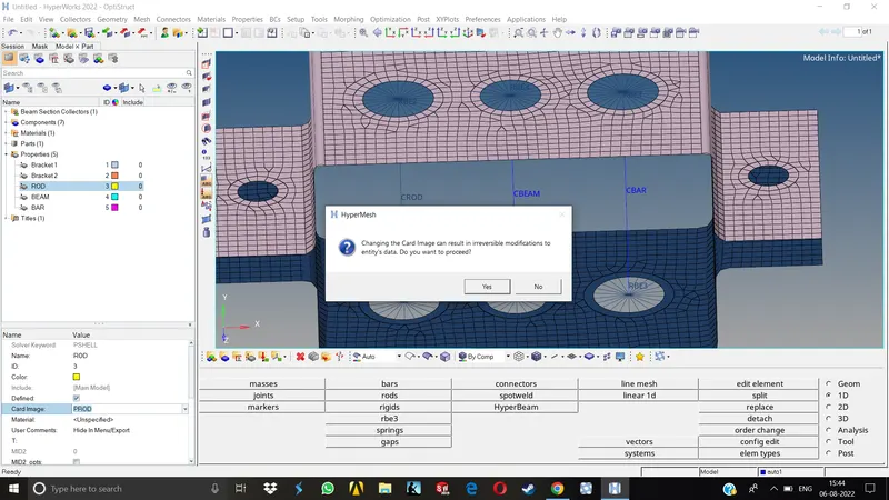
9.Now go to these properties one by one and assign them Card image, Material & Beam sections. For Rod choose Card image as PROD, Material as steel, Beam sections as we created in hyperbeam . Same for Beam & Bar.Once we assign them here, we need to go to each element indivisually and update the properties in 1D section.
10.Go to 1D>Rods>Update>Property and select the property we just created. Same for Beam and bar component.For bar element we only need to constrain the X & Y Dofs. Go to 1D>Rigids>Update & select the resp. cluster then uncheck the dofs as mentioned and hit update.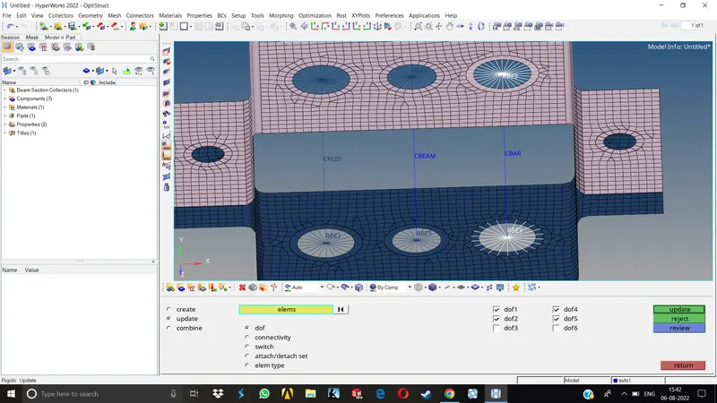
11.Once we've updated all the properties, to be able to see the cross sections we created, we have to change the 1D Traditional element representation to 1D Detailed element Representation.Now all the cross sections can be seen in their true physical dimensions.
Results-
In this challenge, we have successfully learned how to take mid of a simple bracket, meshing it to the specified element type, creating RBE2& RBE3 clusters on specified areas, asiigning them proper masses as specified, creating various 1D elements in Hyperbeam as well as Hypermesh,creating and applying various properties , materials, card images, Proper representation of 1D elements.
Final Model-