Week 4-1D Element Creation Challenge
AIM
Mesh the Given component with the Size of 5 Units. Create 1D elements on the following component with given cross-section and DOF
OBJECTIVE OF GIVEN DATA
- Rod element:- Translational DOF should be Constrained with RBE2 link
Cross-Section: BOX- Dimension a= 12 mm
dimension b=10 mm
Thickness t= 0.75 mm
- Beam element:- All DOF should be constrained with RBE3 link
Cross-Section: I Section- Dimension a= 8 mm
Dimension b= 10 mm
Dimension c= 8.5 mm
Thickness t1= 0.75 mm
Thickness t2= .6 mm
Thickness t3= .6 mm
- Bar element:- Constrain only xand y DOFs With RBE3 link
Cross-section: X section- Dimension DIM1= 5 mm
Thickness DIM2= 1.2 mm
Dimension DIM3= 10 mm
Thickness DIM4= 1.2mm
- & e. Apply the massof magnitude 10 with the RBE2 link
- Join the two components with Spring elements
PROCEDURE
AIM
Mesh the Given component with the Size of 5 Units. Create 1D elements on the following component with given cross-section and DOF
OBJECTIVE OF GIVEN DATA
- Rod element:- Translational DOF should be Constrained with RBE2 link
Cross-Section: BOX- Dimension a= 12 mm
dimension b=10 mm
Thickness t= 0.75 mm
- Beam element:- All DOF should be constrained with RBE3 link
Cross-Section: I Section- Dimension a= 8 mm
Dimension b= 10 mm
Dimension c= 8.5 mm
Thickness t1= 0.75 mm
Thickness t2= .6 mm
Thickness t3= .6 mm
- Bar element:- Constrain only xand y DOFs With RBE3 link
Cross-section: X section- Dimension DIM1= 5 mm
Thickness DIM2= 1.2 mm
Dimension DIM3= 10 mm
Thickness DIM4= 1.2mm
- & e. Apply the massof magnitude 10 with the RBE2 link
- Join the two components with Spring elements
Click on the import from the main menu bar and select import geometry.
File---Geometry---File type IGES---Locate file---Import
To Create mid-surface.
- Click on the geometry in the menu bar
- Click on the mid-surface.
- Click on the surface and select the upper bracket
Geom---midsurface---surfs---Upper bracket---Extract
Model---Components---extract bracket---right click---rename.
Now Similarly do it for the other bracket
Now Delete the solid bracket
Now assign properties with each bracket and apply thickness also give material steel.
Upper Surface> 2.0 Thickness Lower bracket---2.5 Thickness.
To create washers on the geometry surface.
Click on the quick edit in the geometry menu bar.
Click on the washer split and select the circular sections on the geometry.
Geom---quick edit---washer split---5---select hole
To create mesh on the surface
Click on the 2D from the menu bar.
Click on the "automesh" and enter the element size as 5
select the mesh type as "quads".
Click create and the mesh forms on the geometry of the geometry surface.
2D---Automesh---mixed---All surface---element size 8
Case 1
Rod element:- Translational DOF should be Constrained with RBE2 link
Cross-Section: BOX- Dimension a= 12 dimension b=10 mm Thickness t= 0.75 mm
Click on the 1D from the menu bar
Select the rigids on the menu
Set element type to RBE2
Select the circular nodes on the washer splits and create the RBE2 links
1D---rigids---independent (Calculate node)---dependent (Multiple node)---by paths---select dof 1, dof 2, dof3---Create
Click on the rods in the 1D menu and select nodes of the RBE2 links.
Constrain the degrees of freedom for translational. \
Click on the create and now the rod appears on the screen between the RBE2 links.
1D---Hyper beam---standard section---thin walled box---create
Case 2
Beam element:- All DOF should be constrained with RBE3 link
Cross-Section: I Section
To create RBE3 link
1D---RBE3---Node (Near Circle)---By path---All Dof---create
.Click on the hyperbeam view.
Click on the "standard section" and select the element type as "I section".
Click on create will be redirected to the hyperbeam view
1D---Hyper beam---standard section---standard I section---Create
Case 3
Bar element:- Constrain only x and y DOFs With RBE3 link
Cross-section: X section
Create the RBE3 Link
RBE3---only 1 and 2 dof---nodes---near circle---Create node
Click on the hyperbeam in the 1D menu bar
Click on the standard section,select the "optistruct" and in element section select the BOX.
Click on create,will be redirected to the hyperbeam view mode
1D---Hyper Beam---standard section---Standard Section library (OPTISTRUCT)---Standard section type (CROSS)---Create
APPLYING PROPERTIES TO 1D ELEMENTS
To apply property for ROD
Right click---property---Rename to ROD---Change card image to PROD---Material---Steel---BEAM Section---ROD
To update the Bar element
1D---rods---update---property = ROD---update
To Apply Property to BEAM
Right click---property---Rename to BEAM---Change card image to PBEAM---Material---Steel---BEAM Section---BEAM
To update the Beam element
1D---Bars---update---Property BEAM---element type CBEAM---update.
To Apply property to BAR
Right click---property---Rename to BAR---Change card image to PBAR---Material---Steel---BEAM Section---BAR
1D---Bars---update---Property BAR---element type CBAR---update.
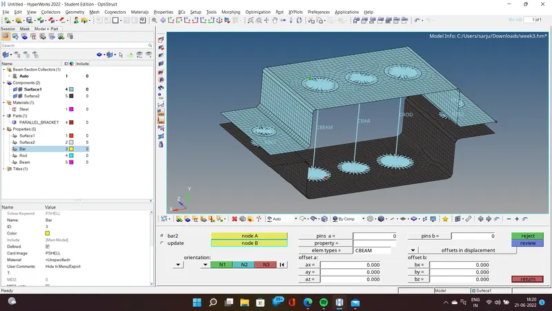
To apply Mass of magnitude 10 with REB2
Create REB2 Link
Go To 1D---Rigids---independent (Calculate node)---dependent (Multiple node)---by paths---Create 1D---masses---MASS = 10---Element type (CMASS1)---Select the REB2 Link
To apply Spring Load
Create RBE2 link on the corner 2 Circles
1D---Rigids---independent (Calculate node)---dependent (Multiple node)---by paths---Create
To Spring Load on both the side
1D---springs---element type HMSPRING---Select the node both side of (F)---Spring is created.
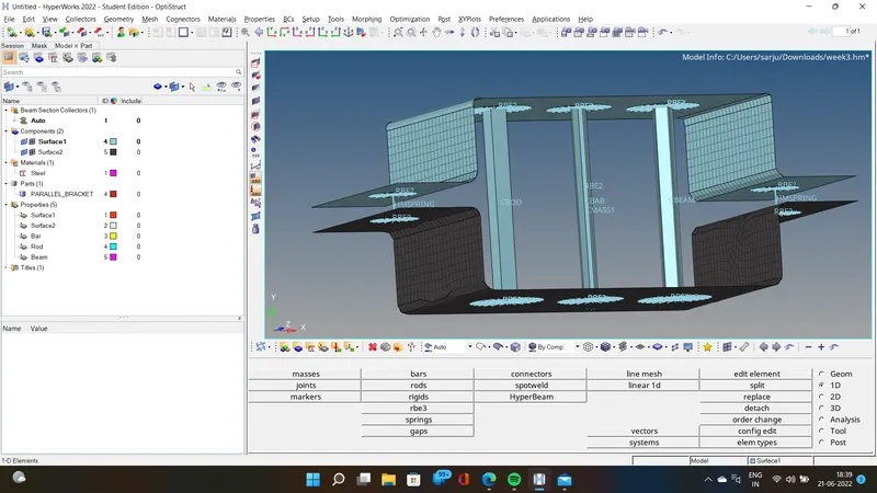
RESULT
Thus the mesh and creation of 1D element has been successfully created as per the given inputs using Hyperworks