Week 4-1D Element Creation Challenge
1D ELEMENT CREATION
AIM
To Mesh the Given component with the Size of 5 Units and Create 1D elements on the following component with given cross- section and DOF .
OBJECTIVES
a. Rod element :- Translational DOF should be Constrained with RBE2 link
Cross-Section: BOX- Dimension a= 12 mm,b=10mm,t=0.75mm
b. Beam element :- All DOF should be constrained with RBE3 link
Cross-Section: I Section- Dimension a= 8 mm,b=10,c=8.5,t1=0.75,t2=.6,t3=.6mm
c. Bar element :- Constrain only x and y DOFs With RBE3 link
Cross-section: X section- Dimension DIM1= 5 mm,DIM2=1.2mm,DIM3=10mm,DIM4=1.2mm
d. & e. Apply the mass of magnitude 10 with the RBE2 link
f. Join the two components with Spring elements .
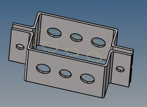
CAD
PROCEDURE
- Go to import >> Import geometry >> file type=IGES >> select the file and import the geometry .
- Go to Delete >> lines >>all>>Delete entity and turn off the display fixed point options .
- Go to Geom>>midsurface>>surfs>>select the upper bracket and Extract for midsurfacing the upper bracket.
- Rename the middle surface to upper bracket and assaign a colour from model view .
- Create a component named midsurface 2 and assaign another colour for the same .
6. Create midsurface for the lower bracket by the same procedure .
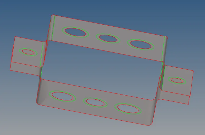
7. Go to Tool>>organise>>surf>>select the lower midsurface>>Move . This is done to ensure that meshing is done
separatly to two extracted midsurfaces .
8. Create a steel material from the entities .
9. Create proper washer splits on required portions by Geom >> Quick edit >>select circles>>give ofset value as 5.
10. Go to 2D >> Automesh >>surfs >> all >> element size=5>>mesh >>return for meshing the components.
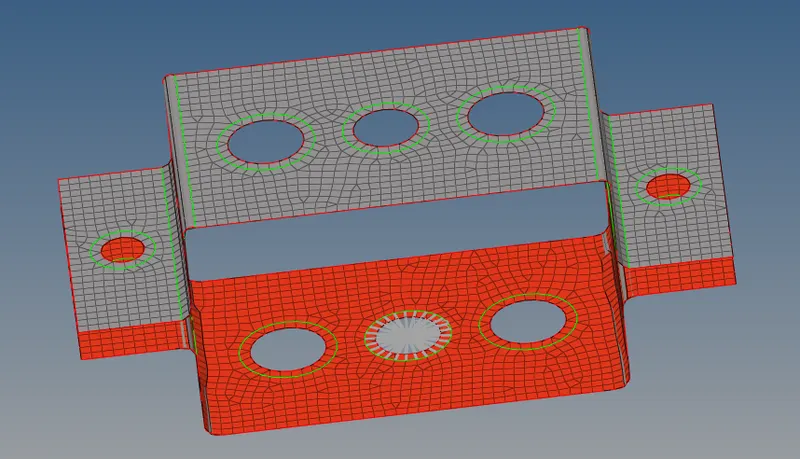
FOR CREATING ROD ELEMENT
- Go to 1D>>rigids>>select nodes>>apply given dof >>create
- Create a BOX section in hyperviews in given dimensions by 1D>>Hyperbeam>>std section>>hypermesh>>box section .
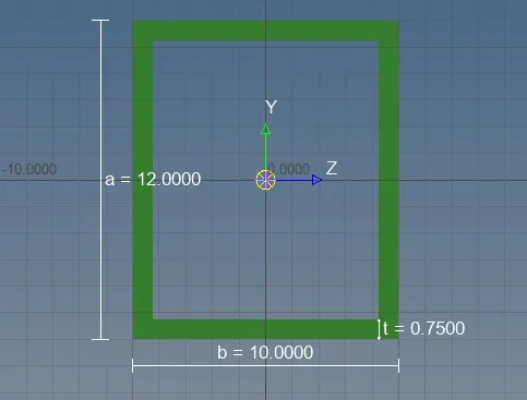
- Create a component named C_BOX for assaigning property and meterial from model .
- Create a rod elements between the RBE2 by 1D>>RODS>>elem type=CROD>>select the nodes in a region
- Create a property named C_ROD_BOX for the rod element .
- Create the property from the toolbar by property>>type=1D>>prop name>>card image=PROD>>Material=steel>>create
- Assaign this property and material = steel for the created component C_BOX .
- Assaign Card image=PROD ,material=steel and beam section as created BOX section for the property created C_ROD_BOX .
- Turn On the 1D Detailed representation and the rod is created as given dimensions .
FOR CREATING BEAM ELEMENT
- Go to 1D>>rbe 3>>select nodes>>apply given dof >>create
- Create a I- section in hyperviews in given dimensions by 1D>>Hyperbeam>>std section>>hypermesh>>I - section .
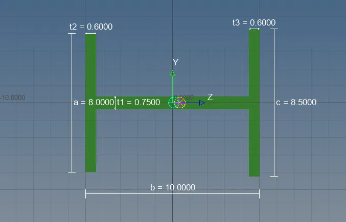
- Create a component named 1D for assaigning property and meterial from model .
- Create a rod elements between the RBE3 by 1D>>BARS>>elem type=CBEAM>>select the nodes in a region
- Create a property named C BEAM for the rod element .
- Create the property from the toolbar by property>>type=1D>>prop name>>card image=PBEAM>>Material=steel>>create
- Assaign this property and material = steel for the created component 1D .
- Assaign Card image=PBEAM ,material=steel and beam section as created I - section for the property created C BEAM .
- Turn On the 1D Detailed representation and the BEAM is created as given dimensions .
FOR CREATING BAR ELEMENT
- Go to 1D>>RBE3>>select nodes>>apply given dof >>create
- Create a X - section in hyperviews in given dimensions by 1D>>Hyperbeam>>std section>>OptiStruct>>CROSS.
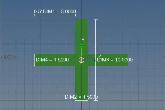
- Create a component named C BAR for assaigning property and meterial from model .
- Create a rod elements between the RBE3 by 1D>>BARS>>elem type=CBAR>>select the nodes in a region
- Create a property named C_BAR_CROSS for the BAR element .
- Create the property from the toolbar by property>>type=1D>>prop name>>card image=PBAR>>Material=steel>>create
- Assaign this property and material = steel for the created component C BAR .
- Assaign Card image=PBAR ,material=steel and beam section as created X - section for the property created C BAR .
- Turn On the 1D Detailed representation and the BAR is created as given dimensions .
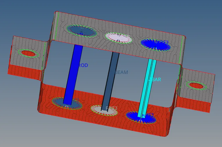
FOR APPLYING MASS
- Go to 1D>>Rigids>>multi nodes>>select nodes>>create nodes around washer split regions in d & e .
- Go to 1D >>Masses>>mass=10>>elem type=CMASS 1>>select the nodes corresponding to rbe2>>create .
- similarly assaign mass for node in other side of bracket region
JOINING THE COMPONENTS WITH SPRING ELEMENTS
- Create a property named ELASTIC for the spring element and change card image to PELAS .
- Go to 1D>>springs>>elem type>>CELAS1>>select the corner nodes >>spring element is created in the region
- similarly create the spring element in other side of the bracket too.
- Go to 1D>>springs update>>property=ELASTIC>>select the elements>>tick the dofs and property .
- Finish the work and save the file using a suitable name .
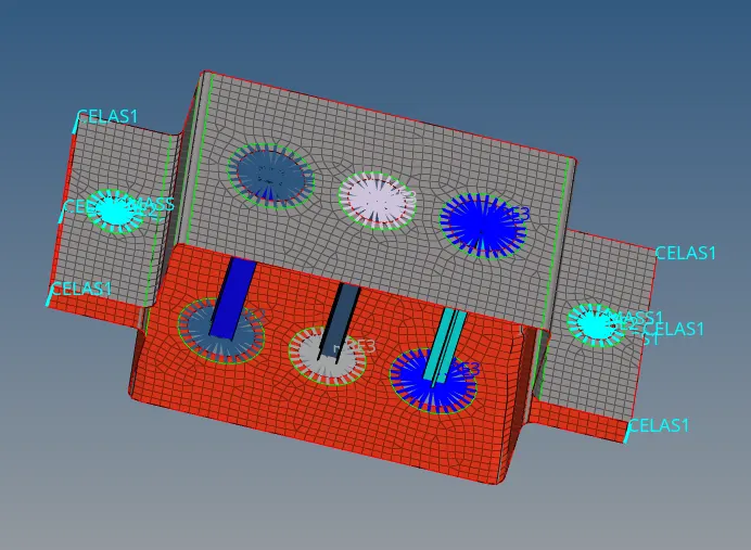
RESULT
Created various 1D elements Bar,Rod,Beam and Spring elements as per given dimension and required DOFs