Week 4-1D Element Creation Challenge
Aim:
Mesh the Given component with the Size of 5 Units. Create 1D elements on the following component with given cross-section and DOF
objective:
- Rod element:- Translational DOF should be Constrained with RBE2 link
Cross-Section: BOX- Dimension a= 12 mm
dimension b=10 mm
Thickness t= 0.75 mm
- Beam element:- All DOF should be constrained with RBE3 link
Cross-Section: I Section- Dimension a= 8 mm
Dimension b= 10 mm
Dimension c= 8.5 mm
Thickness t1= 0.75 mm
Thickness t2= .6 mm
Thickness t3= .6 mm
- Bar element:- Constrain only xand y DOFs With RBE3 link
Cross-section: X section- Dimension DIM1= 5 mm
Thickness DIM2= 1.2 mm
Dimension DIM3= 10 mm
Thickness DIM4= 1.2mm
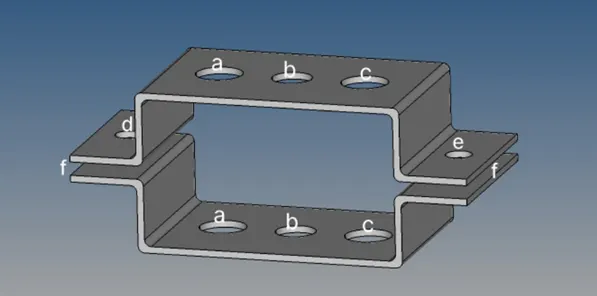
Introduction:
- 1D elements can be applied to 2D and 3D models by analysing the individual line elements that from the models finite elements mesh.
- 1D elements are useful for simulating how different sections of the mesh will react to certain condition.
- 1D elements are basically line shaped elements which are created by two nodes. Examples: RBE2, RBE3, Rod ,Bar, Beam ,Spring elements.
- 1D elements are used when one dimensional is comparatively very large than the other two. i.e long shafts, beams ,joints, pin joints, connection elements
Step wise procedure:
1: first of all import the CAD model through import option.
(import solver deck>import geometry>model name).
Once u import the model it will import the wire frame of that particular model
Then click on the the shaded view. It will show shaded view.
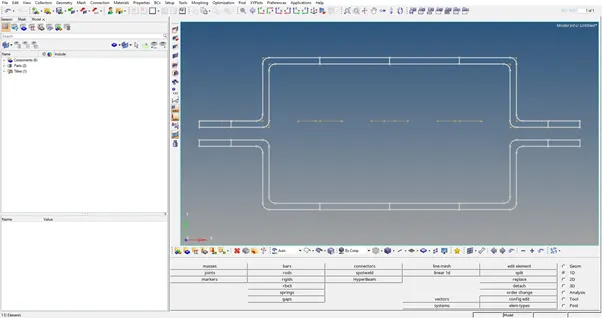
fig.Wire frame view
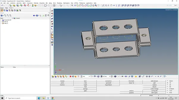
fig.Shaded view
2: Next to crate mid surface , Go to ( geom >mid surface >select surface>extract).mid
surface is means surface between two surfaces,there is one surface on top and another surface.
Lets assume there is no mid surface and we gonna mesh the entire component, now the component is mesh in 3D because it’s a 3D component ,now if u create 3D mesh here for example tetra and hexa the number of nodes is going to be increase and the number of element is also increase which is in terms storage page required to store the entire components and as well as processing power needed to analyse the entire component to avoid all this mid surface is created where u can just represent the entire 3D model by the surface and create a shell elements .Shell elements are the 2D representation of the 3D elements .
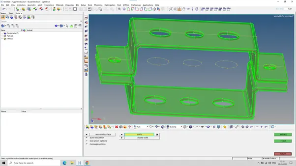
fig.midsurface
3: now move this midsurface to brackets.(tool>organise>select surface>move)Se whatever u have select is bracket 2 make sure for that which is the current component.
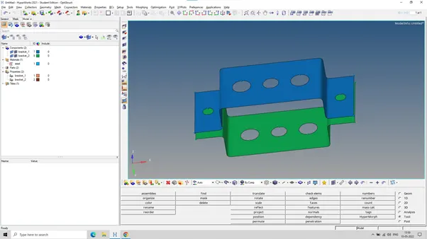
fig.Bracket 2 create
This midsurface will be a 2D representation of the 3D component so how it will a 3D representation,first we assign the material for this component (create>material>steel) then you have to select card image which is based on the solverNext assign the property to that particular material (property>bracket 1>bracket2) next click on the bracket 1 and define the thikness and make sure this is the shell element and material is steel . and assign this to component also, just assign the property and it will assign the material also
4: To do automesh before that we have to crate washers split just go to click edit > washers split click on the circle and it will create (2D>automesh>select surface).
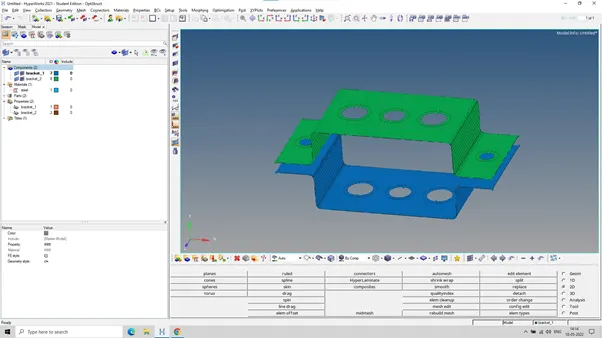
fig.2D mesh
5: we are looking to rigid elements , this are basically RBE2 elements which have infinite stiffness it means never bend , it will never rotate and never move from that particular node, you can only move the nodes hidden that ,the entire elements is gonna stay together ,but in RBE3 elements ,it can be move left right up down move forward and backward and the load distribution is different . the difference between both the elements is RBE2 element can distribute the load to each and equal direction irrespective of their position and distance from the independent load , but in RBE3 load distribution is difference and its not exactly uniform first to create multiple nodes (rigids>multiple nodes>by path)
6:hyperbeam is basically use to creating the beams cross sections (standard section>hyperbeam/optistrct>cross section>box section>I section)and define dimension given in the questions
Cross-Section: BOX- Dimension a= 12 mm
dimension b=10 mm
Thickness t= 0.75 mm
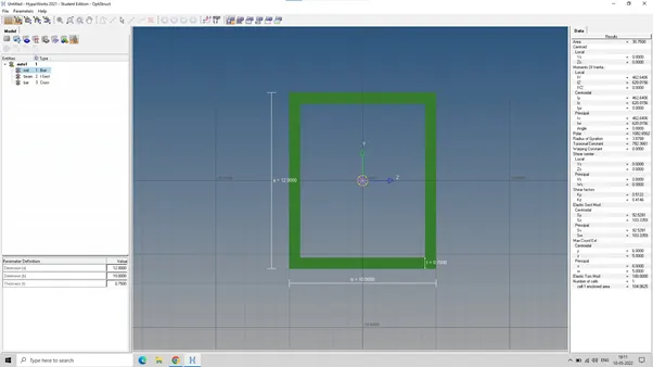
fig.rod box section
Cross-Section: I Section- Dimension a= 8 mm
Dimension b= 10 mm
Dimension c= 8.5 mm
Thickness t1= 0.75 mm
Thickness t2= .6 mm
Thickness t3= .6 mm
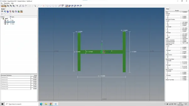
fig.Beam I section
Cross-section: X section- Dimension DIM1= 5 mm
Thickness DIM2= 1.2 mm
Dimension DIM3= 10 mm
Thickness DIM4= 1.2mm
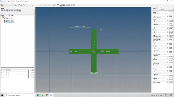
fig.Bar X section
7: lets create a bar elements (bar>first node >second node >cross section)To do similar rod and beam same process is to be do.once the rod, bar and beam is create we have to give cross section to them ,create property for bar, rod and beam ,now select the property and assign card image PROD,PBEAM,PBAR after that assign cross sections bar, rod and beam and update those propertiesFor rod bar and beam .(bar>update>select property >update).
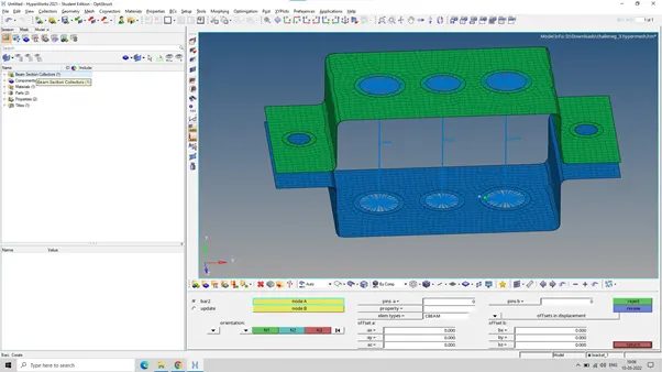
Next go to 1D traditional element representation and we have given the cross section
Results:
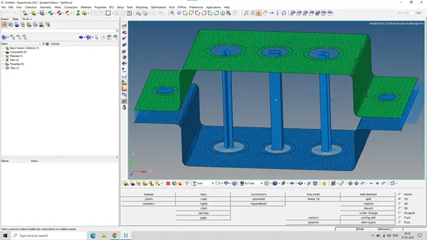
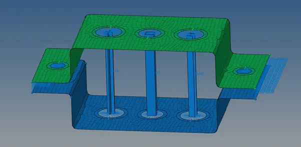
- & e. Apply the massof magnitude 10 with the RBE2 link
- Join the two components with Spring elements.