Week 4-1D Element Creation Challenge
AIM : FOR THE GIVEN COMPONENT, EXTRACTION OF MIDSURFACE WHICH IS THEN TO BE MESHED AND FOLLOWED BY 1D ELEMENT CREATION WITH THE SPECIFIED CROSS SECTIONAL DIMENSION AND DEGREE OF FREEDOMs USING HYPERWORKS (OPTISTRUCT).
INPUT : The input for the aforesaid operation is a geometry of PARALLEL BRACKET in IGES format, which is then imported in HYPERWORKS.
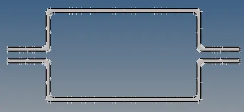
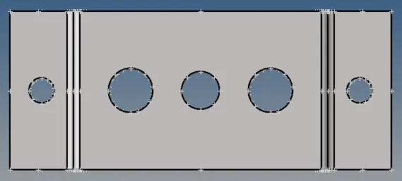
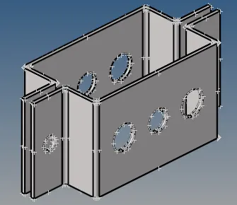
WORKING PROCEDURE :
- EXTRACTION OF MIDSURFACE ;
- The process of MIDSURFACING varies depending upon the component's thickness and complexity, since our working model is of UNIFORM THICKNESS, the midsurfacing of which is quite simple.
- To extract the midplane we need to go to GEOMETRY>MIDSURFACE>AUTOEXTRACTION, and by selecting both the part's surface, we'll get the required mid plane to work on.
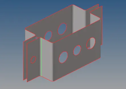
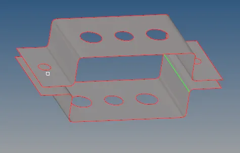
- As we can observe here, both the midplanes are clubbed as one, which is not desired, hence we need to separate as TOP and BOTTOM.
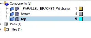
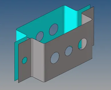
- For that we need to create a separate component as TOP/BOTTOM.
- This organising of midplanes as different components in TOP/BOTTOM can be done using TOOLS>ORGANISE>MOVE.
- CREATING AND ASSIGNING MATERIAL AND PROPERTY ;
- The next step is to create MATERIAL as well as PROPERTY, the material can be created using RMB>CREATE>MATERIAL,
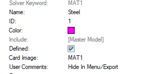
- The material has now been created. Now the property is created for both TOP/BOTTOM using RMB>CREATE>PROPERTY, given name as PROP1 and PROP2 as PSHELL, and assigned to the components and material created, shown below;
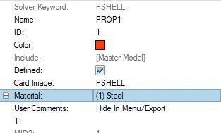
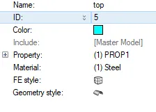
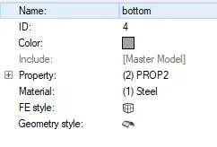
- GEOMETRICAL CLEANUP AND 2D MESHING AS PER GIVEN CRITERIA;
- Before meshing the shell, its required to clean the geometry as per given criteria, here the only criteria is the target element size of 5, which is to be fed and processed using GEOMETRY>AUTOCLEANUP, shown below;
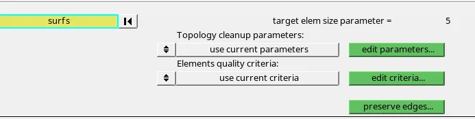
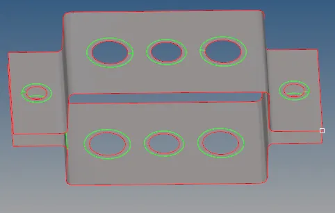
- As we can observe, geometry is cleaned up as per the required element size and the WASHER LIMIT has also been deployed for the better mesh flow and less STRESS CONCENTRATION near the holes.
- The model is now forwaded for 2D meshing, which is done using 2D>AUTOMESH, and by feeding ELEMENT SIZE as 5 units, and selecting the MESH TYPE as MIXED.
- By selecting the displayed surfaces, the mesh is deployed, the result obtained is shown below;
-
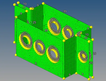
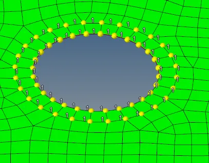
- As we can observe, the features are not properly captured resulting in poor mesh flow near features, shown below;
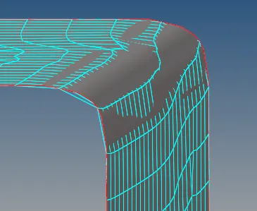 To fix this, manual intervention is needed.
- These featuring capturing is done by taking reference of parent component to PROJECT FEATURE LINE TO THE MIDPLANE.
- The same is done using GEOMETRY>SURFACE EDIT>TRIM WITH LINES, and by selecting surface and corresponding feature line and trim, the result is shown below;
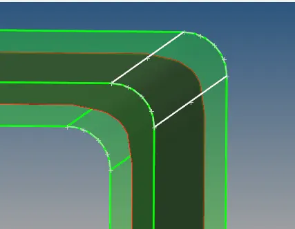
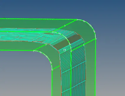
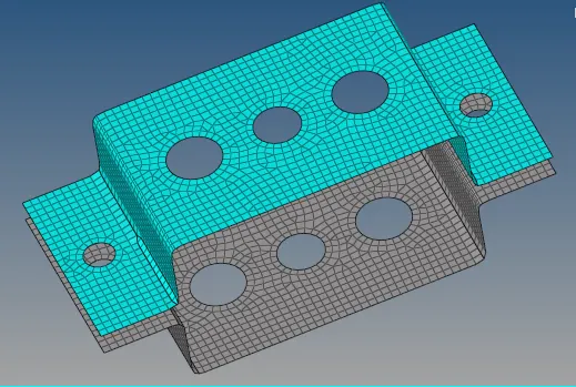
- The same is done for all the feature surfaces.The final meshed output is shown below;
-
- CREATING ROD ELEMENT AND ASSIGNING ITS CROSS SECTION:
- As it is required to create ROD element with translation DOFs constrained with RBE2 LINK.
- RIGID BODY ELEMENTS are the elements having infinite value of STIFFNESS.
- In RBE2 elements, the load distribution is uniform whereas in RBE3 its not uniform instead weighted.
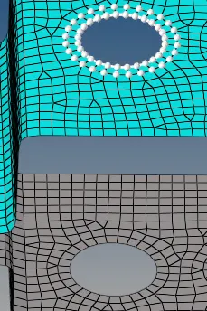
- RBE2 link has to be created at the localised spot, which is done using 1D>RIGIDS>CREATE, and by selecting ELEMENT TYPE as RBE2 , now selecting the CALCULATED NODE OPTIONS WITH LOOP and having 1 LAYER, to select the nodes across washer limit as well in one go, shown below;
-
-
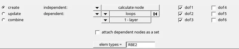
- Only TRANSLATION DOFs are required to be constrained with RBE2 link thus rotations are allowed.
-
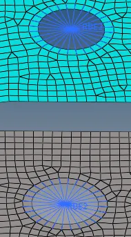
- As the RBE2 links are created at the both the localised ends for the ROD element. now the ROD element has to be created at the assigned spot.
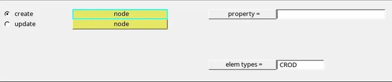
- The ROD element is created using 1D>RODS>CREATE, and by selecting master nodes and selecting ELEMENT TYPE as CROD,shown below;
-
-
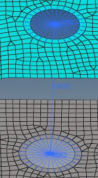
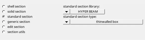
- As the element is created, now the cross section for the same has to be designated. For defining the cross section, we go to 1D>HYPERBEAM>STANDARD SELECTION. here we further choose the option for ROD cross section as thin walled box, as we click create, we'll be redirected to HYPERBEAM section to further input the specified dimensions a = 12, b = 10, t = 0.75 , shown below;
-
-
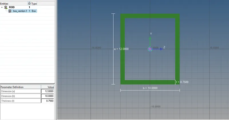
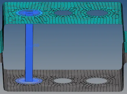
- Now returning to the model view, where we can see the cross section is reflected in BEAM SELECTION COLLECTORS, now we need to create a property ROD as PROD and assign the beam section to it and also update the property in ROD, which will further reflect in 1D DETAILED ELEMENT REPRESENTATION. Shown below;
-

-
- CREATING THE BEAM ELEMENT AND ASSIGNING ITS CROSS SECTION;
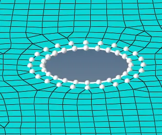
- RBE3 link is to be created with all its DOFs constrained, which is done using 1D>RBE3>CREATE DEPENDENT, and by selecting LOOP with 1LAYER for washer splits.Shown below;
-
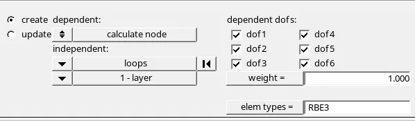
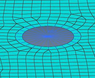
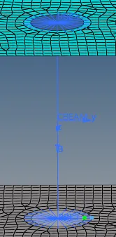
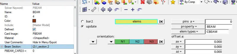
- Now the BEAM element is to be created using 1D>BAR>BAR2. By selecting master nodes of RBE3 and selecting element type as CBEAM and giving orientation, shown below;
-

-
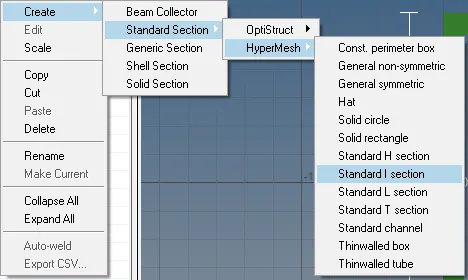
- Now for the cross section, we again go to the HYPERBEAM view, where we can create a new cross section as standard I section which specified dimensions, shown below;
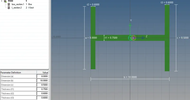
- Similarly we need to create a property named BEAM as PBEAM, and assign its respective cross section and update the BEAM element.
-
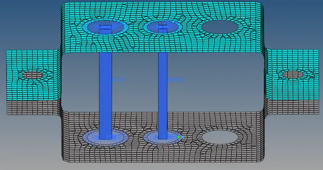
- The beam cross section will reflect in the model as shown below;
-
- CREATION OF BAR ELEMENT AND ASSIGNING ITS CROSS SECTION;
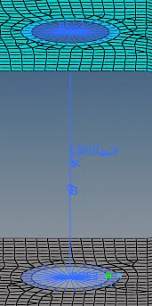
- RBE3 link is to be created with X and Y DOFs constrained i.e movement is only allowed in z direction. Then BAR element is created using 1D>BARs>BAR2, and by selecting element type as CBAR. The result shown below;
-
- Now using HYPERBEAM, cross section for the BAR is specified;
-
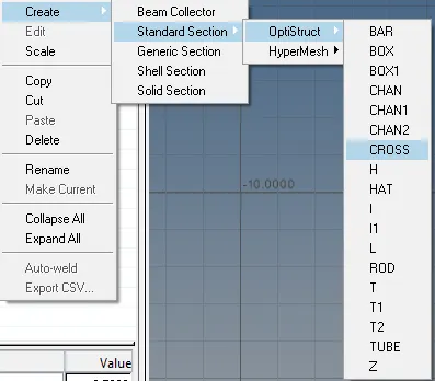
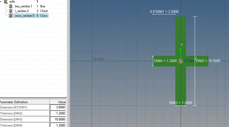
- PROPERTY is assigned as PBAR to the bar element and updated as well;
-

-
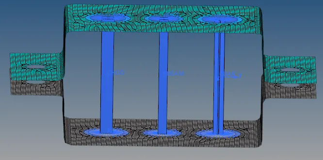
- ASSIGNING THE MASS WITH RBE2 LINK;
- RBE2 has to be created first and then at the master node the mass has to be assingned of magnitude 10. Mass is assign using 1D>MASSES>CREATE.
- Magnitude and property is to be fed, and the element selection is CMASS1. the control is shown below;
-

- CONNECTING TOP AND BOTTOM BRACKET WITH SPRING ELEMENT;
- Spring elements are elastic elements, which is created using 1D>SPRING, and by selecting NODES.
- The element type selected is CELAS1,
-

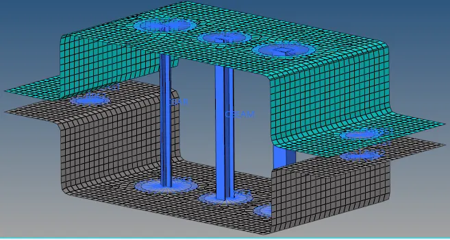
- The final output is shown below with different orientation;
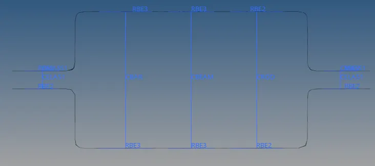
- RESULTS :
- The given component is imported and its midsurface is extracted.
- midsurface is extracted and cleaned.
- 2D meshing is done over it with given meshing criteria.
- Various 1D elements are created and assigned to localised spots sprecified.
- CONCLUSION :
Almost every kind of 1d elements are created, which helped in establishing the understanding and skill of these elements their DOFs and their various application.