Week 4-1D Element Creation Challenge
Aim: To mesh the given component with element size as 5units and create 1D elements on the following componentwith given cross-sections and DOFs.
Procedure:
- Import the given IGS file into HyperWorks and open the model from downloads and import.[command:Import-Geomentry-select the file-Import].
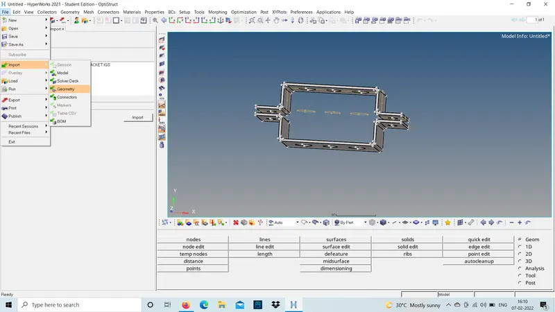
- For the given model parallel bracket extract the mid-surface.
MID-SURFACE EXTRACTION:
Step1:
- Use mid-surface from Geom and auto midsurface option to extract mid-surface for the model.
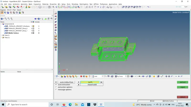
- now,select extraction options and select the type as skin offset and select the surface to extarct.
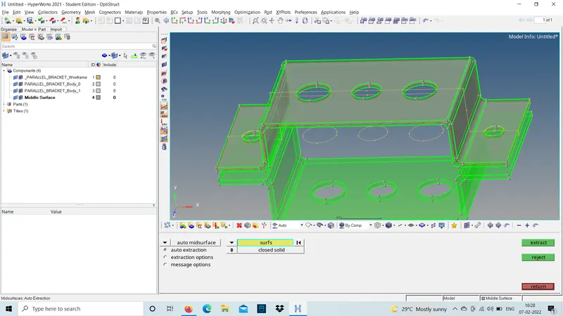
- skin offset is selected for this model because the fillets and surface capturing will be attained by using skin offset and rename the extracted mid-surface.
- The name mid-surface it self says the surface between the surfaces.so,that the Dimensions can be mentioned in the property card.
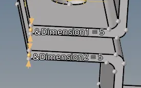
- similarly do the same for the lower bracket as well and rename the model.
Step2:
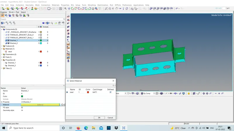
- This bracket is made of steel.so,we should select the type of material used by creating a new material property as steel.

Step3:
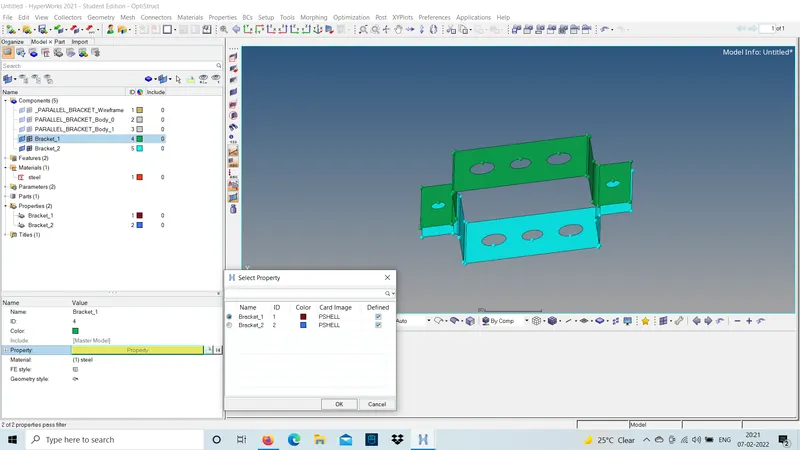
- The property for the brackets should be created by specifying the material ass well as property for the parallel bracket.so,a component should contain the material used as well as the thickness and property assigned to it.
NOTE: Here,Two properties should be assigned for bracket1 and barcket2 even though the thickness parameters are same seperate property card should be created.

Step4:
- now,the created property card and material card should be assigned to the component .[command:component-Bracket_1-material and property-click ok].
property card Material card
Step5:
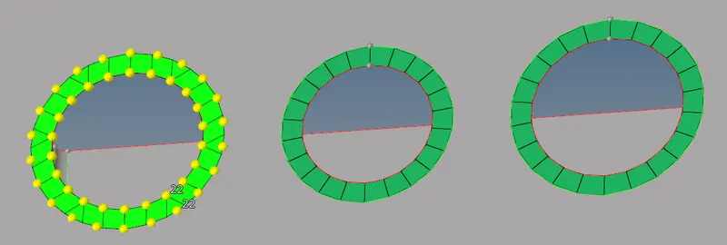
- This is a basic model so need to do autoclenup just provide a washer split for the hole area and specify the offset value to 5mm. so, that we can diploy the connections using the nodal capturing.
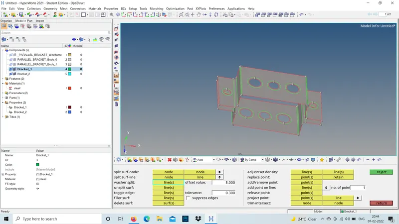
- 2D MESH GERERATING: The 3D model is dismantled to 2D by neglecting any one dimension considering the xand y and neglecting z we create a mid-surface and this is done because any one side is less comparing to the other two and 2D mesh is done with SHELL elements .so,the storage capacity as well as the run time will be less for 2D mesh.
Step1:
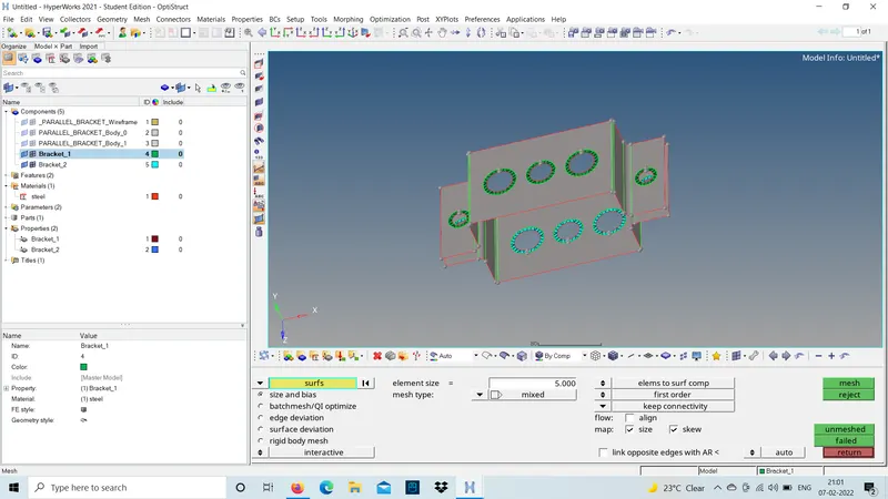
use 2D automesh and selct the element size as 5 units and mesh type as mixed type.now,first select the washer zone and mesh.[command:2D mesh-automesh-mesh type and mesh size-mesh].
Step2:
- To attain a proper mesh flow we can just increase or decrease the nodes .make sure that the nodes should be even number:like 2,4.6,8,10,12...the capturing will be proper and mesh flow willbe attained.
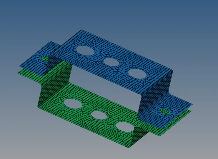
- mesh the remaining ares and achieve proper mesh flow.now using skin offset mid-surface capturing and mesh flow will be proper in the fillet regions as well as the flat regions.
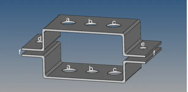
- 1D ELEMENTS OF THE COMPONENT WITH GIVEN CROSS-SECTIONS AND DOFs:
Step1:
- This 1D elements should be created with these paramerts list as shown in the figure below.
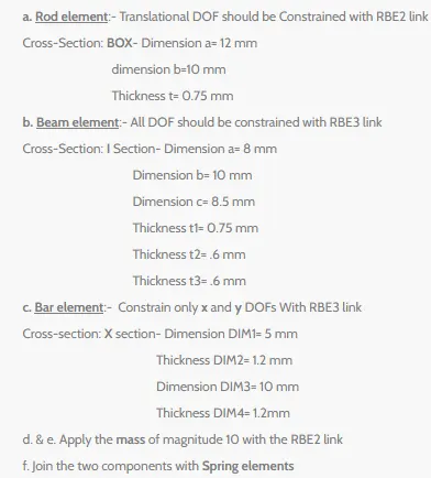
- parameters to be considered,
Step2:
To create 1D elements for the washer area according to the given parameters and to create hyperbeam elements like rod,beam,bar we should first cretae a hyperbeam according to the given parameters at the top.The rigids can be created by using multiple nodes option and nodes can be created by path .[command:1D-Rigids-select the nodes-by path and create].
NOTE:Here,the nodes are created to diploy a rigid 1D elements by selecting the nodes-by path or by elements to select the nodes faster and diploy the rigid connection.
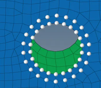
- Before,creating the rigids provide the DOFs for the 1D elements to be diployed according to the given parameters for the washer elements .
a.Rod element.
Step1:
- To diploy Rigid connection for the washer elements for the parallel bracket.
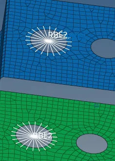
1D-Rigids -create -multiple nodes -select the nodes -provide DOFs-create
for,the washer area' a' to diploy RB2 connection these are the DOFs to be considered :
1.Transulation-x[dof1].
2.Transulation-y[dof2].
3.Transulation-z[dof3]
Step2:
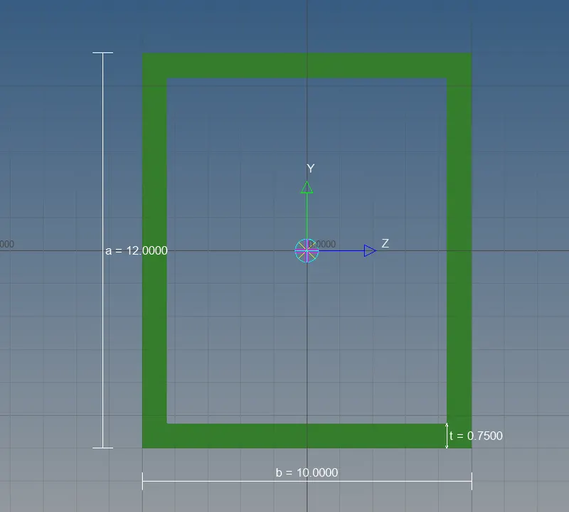
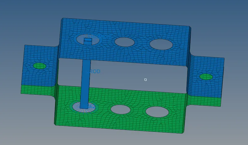
- To create Rod element between the parallel Brackets we should create a hyperbeam solid body according to the given dimensions.
The selected cross-section for Rod element is BOX .[command:1D-hyperbeams-box shape-create].It will directly open the hyperbeam box shape in the graphics area.
- Dimension a=12mm.
- Dimension b=10mm.
- Thickness t= 0.75mm.
Step3:
Now,create a Property card for the Rod element as PROD and provide the material ID as well as the beam section as ROD.
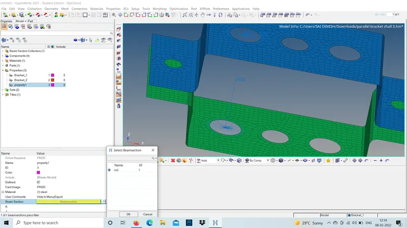
- Turn on the 1D Traditional and detailed element representation to view the model as a solid part.
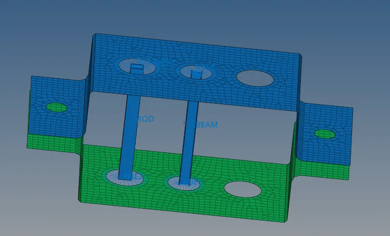
b.Beam element:
Step1:
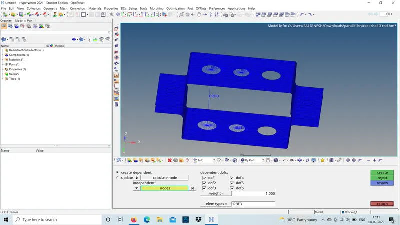
- To diploy RB3 connection for washer area 'b' to the parallel bracket.
1D-RB3-Multiple nodes-select the nodes-by path -create.
- For,the washer area 'b'all the DOFs to be considered.
Step2:
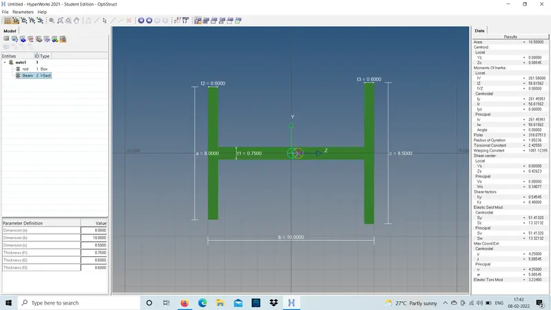
To create Beam element for the washer area 'b' the cross-section is I section should be created using the given parameters in hyperbeam.
Cross-section :I section -Dimension a=8mm.
Dimension b=10mm
Dimension c=8.5mm
Thickness t1=0.75mm
Thickness t2=0.6mm
Thickness t3=0.6mm
Step3:
now,create a propert card for the Beam element as PBEAM and provide the material ID as well as the beam section as Beam and click ok.
create-property-elememt type as PBEAM-material ID-beam section-Beam-ok.
- For,creating the beam elememt we should provide the orientaions and specify the property and crerate.
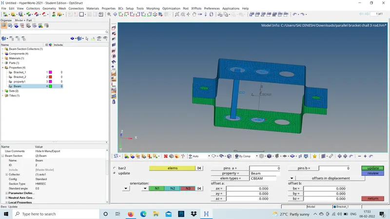
- update the element and turn on the Detail element representation.
c.Bar element:
Step1:
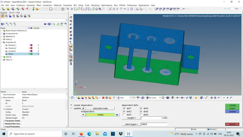
- To diploy RB3 connection for washer area 'c' to the parallel bracket.
1D-RB3-Multiple nodes-select the nodes-by path -create.
- For washer area 'c'constrain only xandy DOFs neglecting z direction.
Step2:
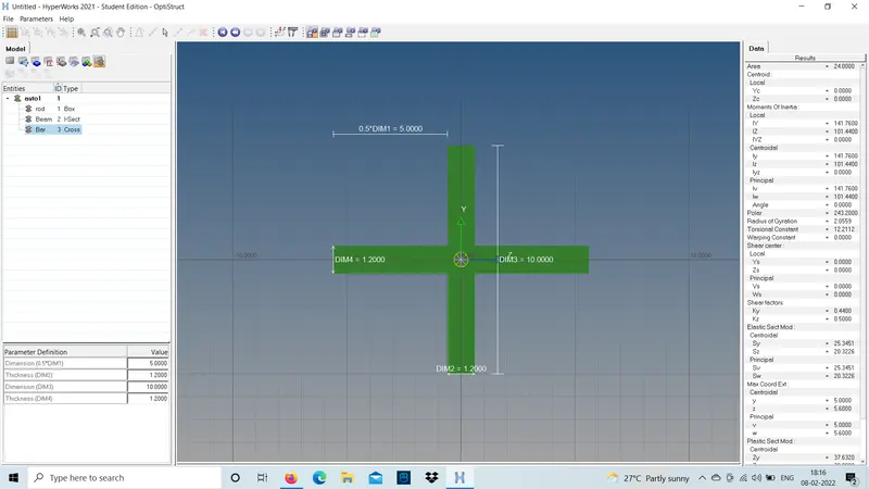
To create Beam element for the washer area 'c' the cross-section is x -section should be created using the given parameters in hyperbeam.
cross section: x-section-Dimension DIM1=5mm.
Thickness DIM2=1.2mm.
Dimension DIM3=10mm.
Thickness DIM4=1.2mm.
Step3:
now,create a property card for the Bar element as PBAR and provide the material ID an as well as the beam section as BAR and click ok.
create-property-element type as PBAR-material ID as steel-beam section as BAR-click ok.
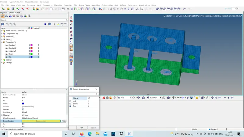
- first selct the two nodes to be diployed -select the orientation nodes-select the property ID -element type as BAR and click ok
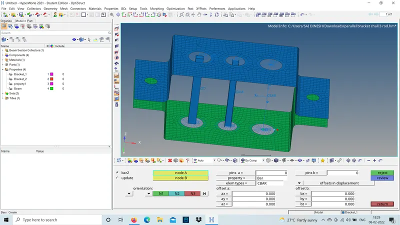
- update the element by selecting all the characterists and create.
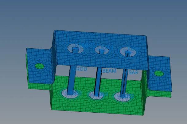
d and e: Rigids connection and applying mass:
- Create a rigid RB2 connection and provide a mass of magnitude 10 at the master node of the cluster RB2.
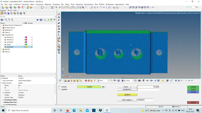
f is to join the two components with a spring elements :
- To join the both brackets and show them as a single part this spring element connection should be diployed.actually this connections are done to because any part should not be floating on air.so,that thsi connection shows it is associated with the model.
- It can be created by selecting the upper node and lower node and create.
1D-spring-select the nodes -create.
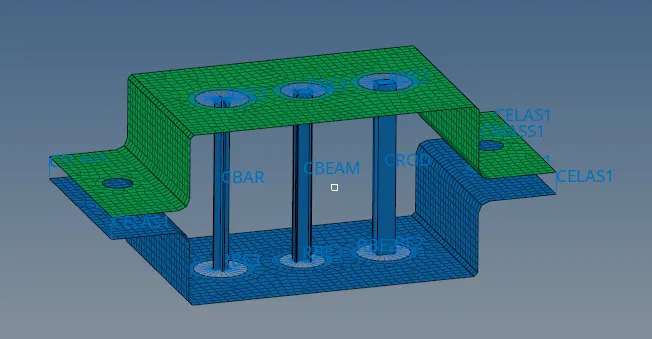
- It will show as a CELAST by creating the connection between the brackets and create a single part as parallel bracket.
- turn on 2D representaion of the model detail representaion of the surface and check the thickness is assigned is correct and check the fillet capturing as well to save the model.
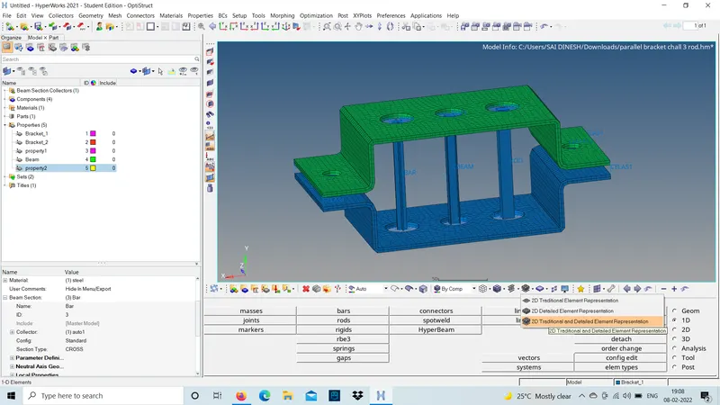
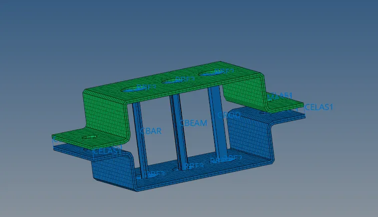
Result:
Mesh the Given component with the Size of 5 Units and Creating 1D elements on the following component with given cross-section and DOFs is done and shown below.
Learning outcome:
- geomentry cleanup using different tools.The use of various surface methods provided like skin offset,offset+planes...etc.
- 2D mesh the compoonent using automesh and reason for creating washer splits and hole or bolt ares.
- 1D elements diployement using the rigids,RB3,rods and bars.
- HyperBeams creating using various cross-sections.
- creating properties and assign them to the model.