Week 4-1D Element Creation Challenge
AIM: 1D Element Creation Challenge
OBJECTIVES:
- Mesh the given component with the element size of 5 Units.
- Create 1D elements of (Rob, Beam, Bar, Mass and Spring) on the given component with given cross-section and DOF.
Q) Mesh the Given component with the Size of 5 Units. Create 1D elements on the following component with given cross-section and DOF
PROCEDURE
- After importing the model create mid-surface and mask the remaining surfaces.
- Assign the material and property for these surfaces.
- Then mesh the mid-surfaces with given element size of 5 units.
- Assign RBE2 and RBE3 links as per the given conditions and create Bar, Beam, Rod, Mass and Spring elements as per the given conditions.
- Apply material and property to these Bar, Beam and Rod elements and show the 3D view.
Imported the given model with 2 Brackets
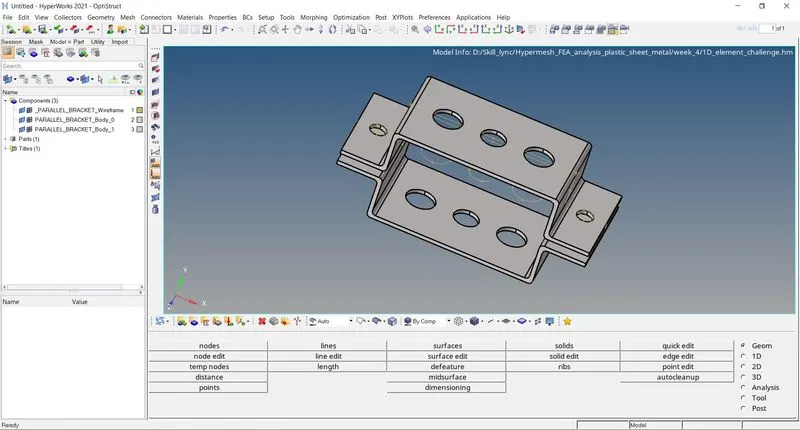
Now, we need to create the mid-surface to these 2 brackets. Go to Geometry > midsurface as shown below.

This is the interface will appear after clicking on the midsurface option. Here select the Top and Bottom blank surfaces and click on Extract.
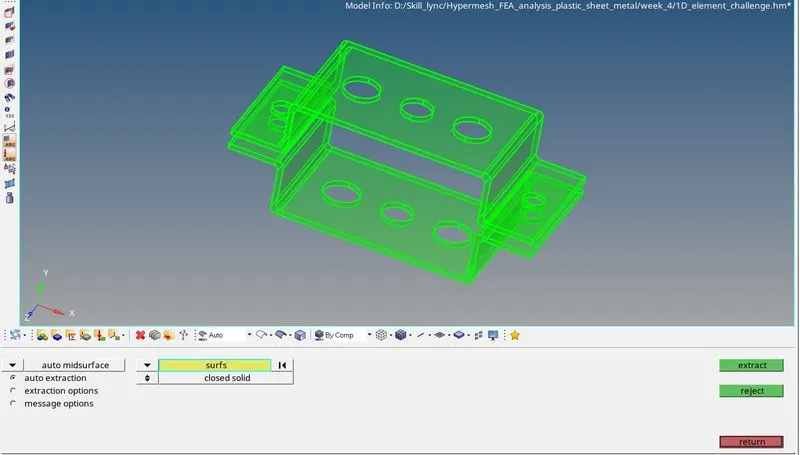
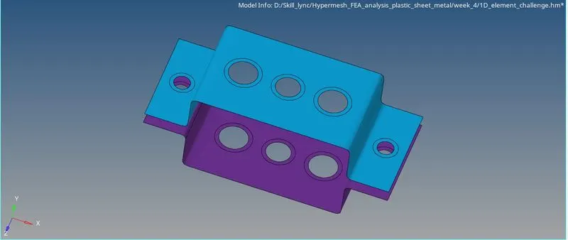
Finally, we have extracted the surfaces and assigned the different colours to if as shown below.
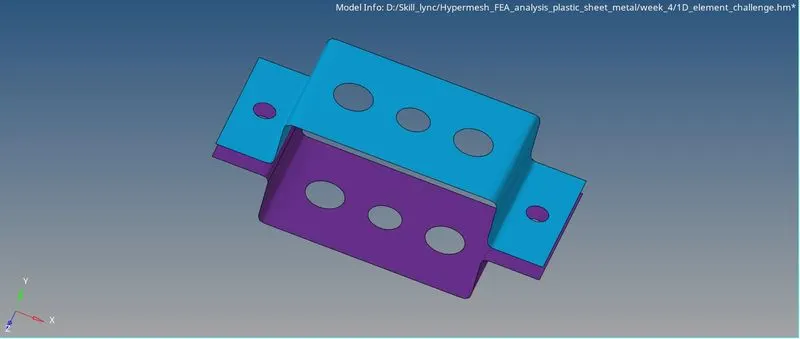
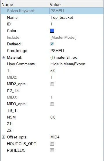
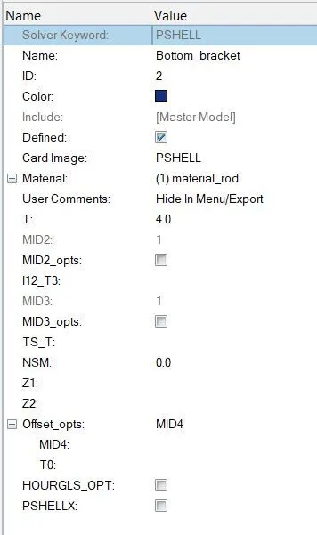
Now we need to assign the properties to these surfaces
Goto Model menu > Right click > Create > Property
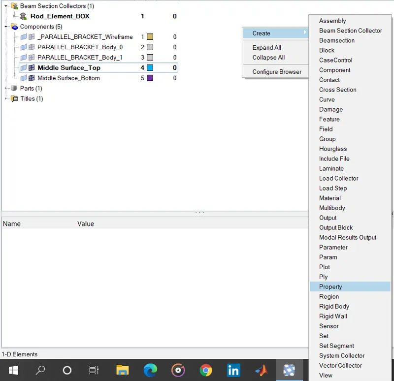
Property assigned for Top Bracket
Property assigned for Bottom Bracket
Before meshing the surfaces apply the split washer around the circular portion.
Goto Geometric tool kit > Quick edit > Split Washer
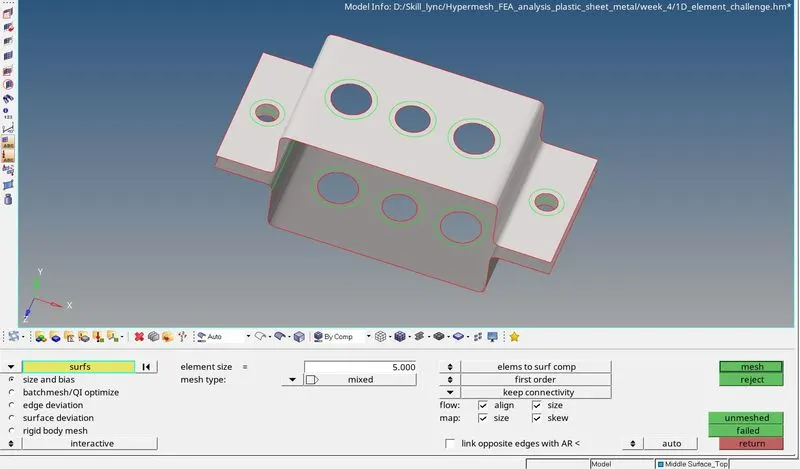
Now, its time to mesh the surfaces. Goto 2D > automesh

First mesh the Top blank by selecting the top surface and element size of the mesh is 5 units
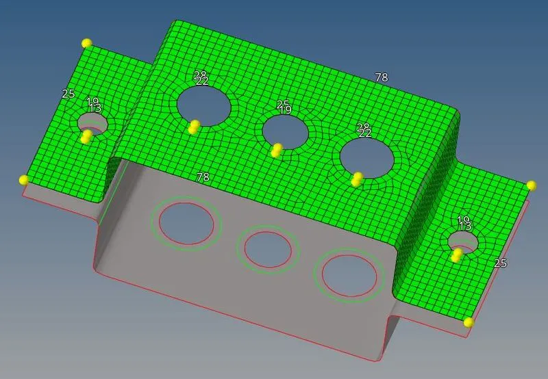
Now, meshed the bottom surface
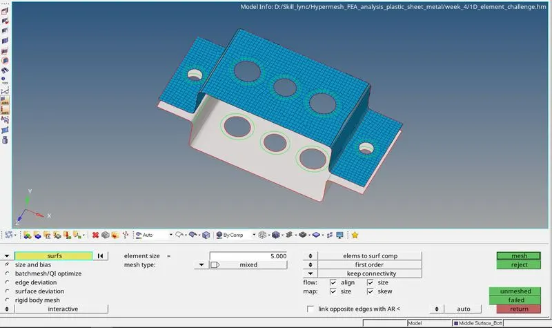
Complete Meshed surfaces.
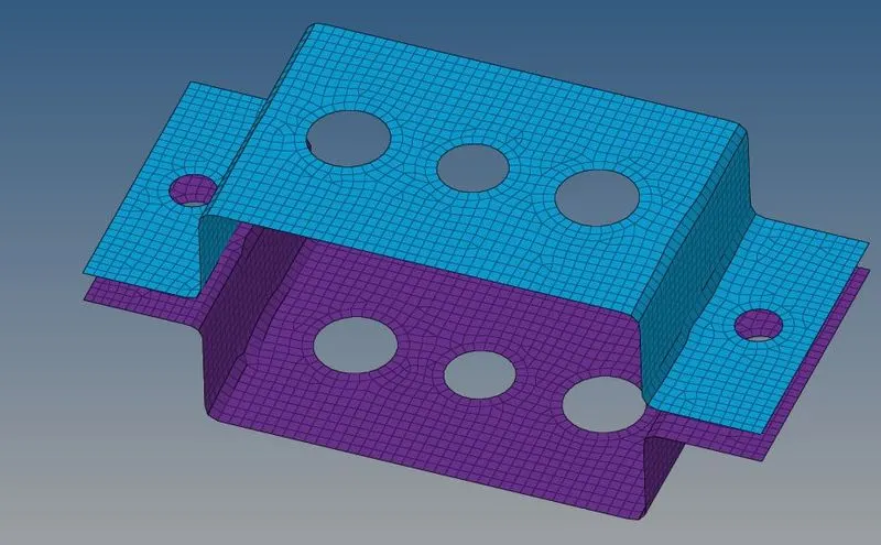
A. Rod element: - Translational DOF should be Constrained with RBE2 link
Cross-Section: BOX- Dimension a= 12 mm
Dimension b=10 mm
Thickness t= 0.75 mm
To create Bar, Beam and Rod 1D elements, first we have to assign these dimensions to these cross-sections in the hyberbeam section.
Goto 1D > Hyperbeam > select standard section > select HYPE Beam in standard section library > select the required cross-section in the standard section type.



After selecting the required standard section type (thickened wall) and assign the required dimensions.
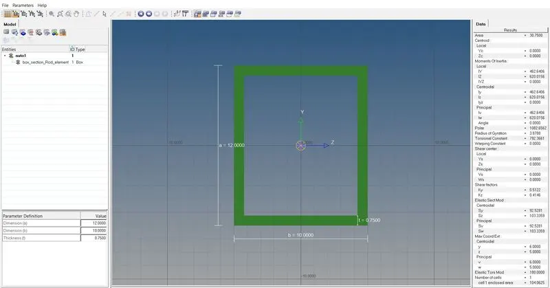
To create rbe2 elements Goto 1D > rigids
Now, select the nodes around the washer and hole to create a set of rbe2 links and constraining the translational DOF.
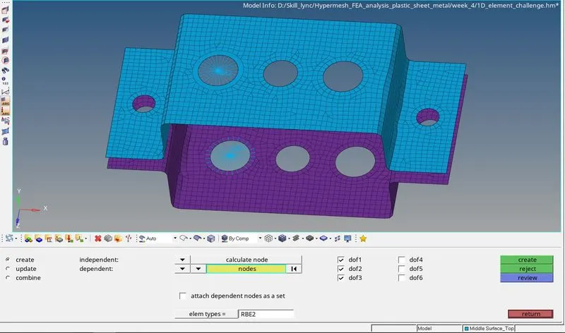
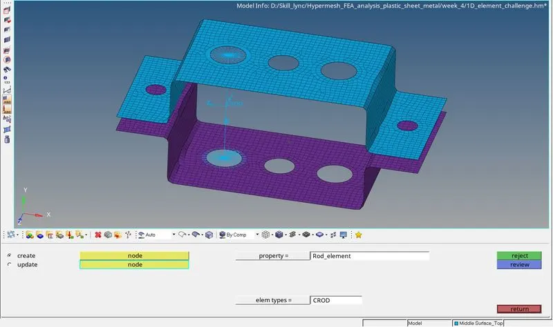
To create the element Goto 1D > rods
Now, select the nodes of rbe2 links and the rod element will be created. Now we can update the property by assigning the property to the rod element.
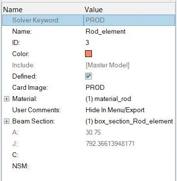
Assigning the property to the rod element
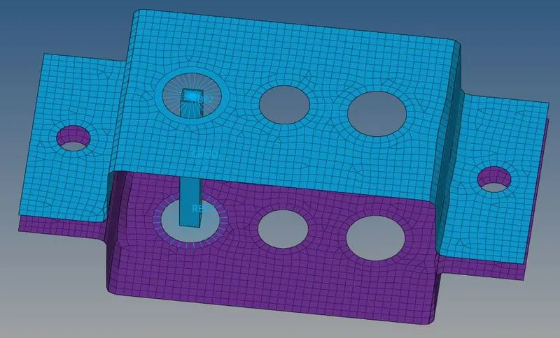
Now, we can see the rod in 3D view
B. Beam element: - All DOF should be constrained with RBE3 link
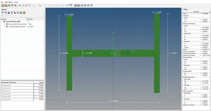
Cross-Section: I Section- Dimension a= 8 mm
Dimension b= 10 mm
Dimension c= 8.5 mm
Thickness t1= 0.75 mm
Thickness t2= 0.6 mm
Thickness t3= 0.6 mm
After selecting the required standard section type (I section) and assign the required dimensions.

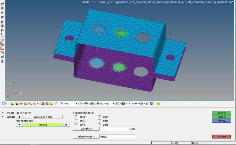
To create rbe3 elements Goto 1D > rbe3
Now, select the nodes around the washer and hole to create a set of rbe3 links and constraining the all DOF.
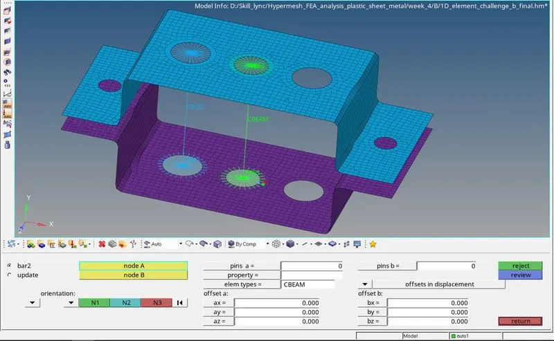
To create the element Goto 1D > bars
Now, select the nodes of rbe3 links, select elem types as CBEAM and the Beam element will be created. Now we can update the property by assigning the property to the beam element.
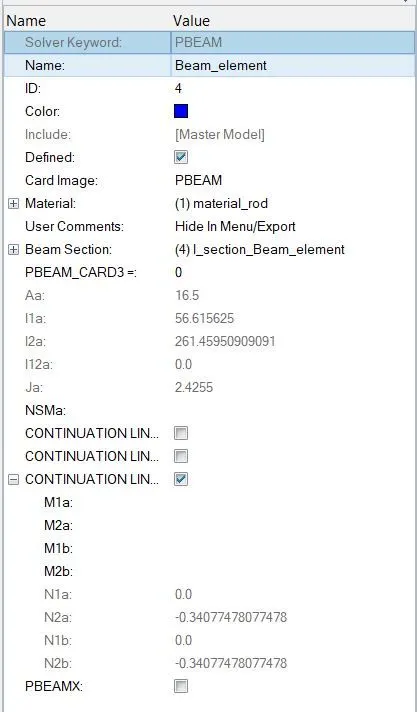
Assigning the property to the beam element
Now, we can see the Beam (I section) in 3D view
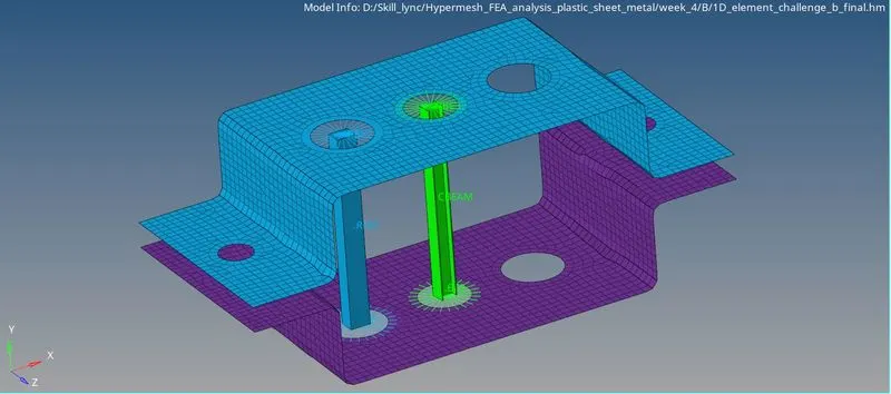
C. Bar element: - Constrain only xand y DOFs With RBE3 link
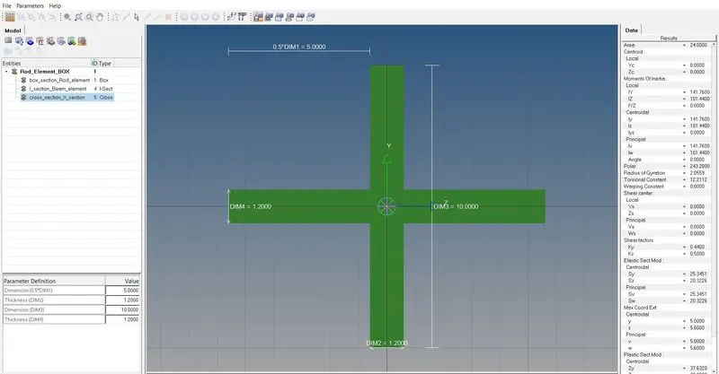
Cross-section: X section- Dimension DIM1= 5 mm
Thickness DIM2= 1.2 mm
Dimension DIM3= 10 mm
Thickness DIM4= 1.2mm
After selecting the required standard section type (X section) and assign the required dimensions.
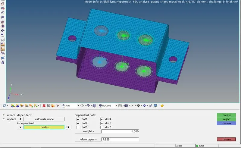
To create rbe2 elements Goto 1D > rbe3
Now, select the nodes around the washer and hole to create a set of rbe3 links and constraining the X and Y DOF.
To create the element Goto 1D > bars
Now, select the nodes of rbe2 links, select elem types as CBAR and the Bar element will be created. Now we can update the property by assigning the property to the bar element.
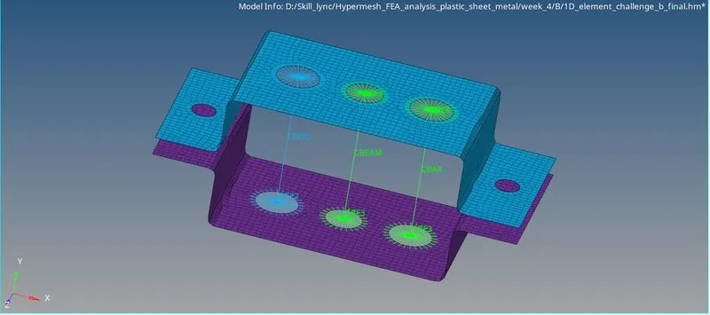
Assigning the property to the bar element
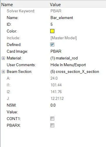
Now, we can see the Beam (I section) in 3D view
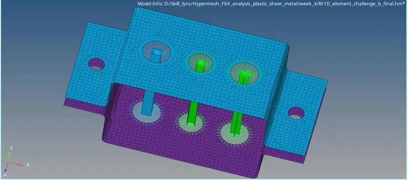
D and E. Apply the mass of magnitude 10 with the RBE2 link
Select the nodes around the washer and hole to create a set of rbe2 links with All DOF constrain.
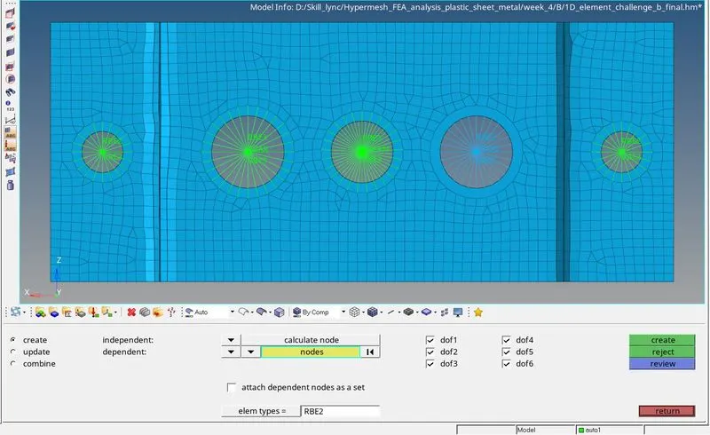
To apply mass magnitude of 10 units. Goto 1D > masses
Select the rbe2 links nodes and selected the property as Rod_element with mass of 10 units. Choose elem types as CMASS1.
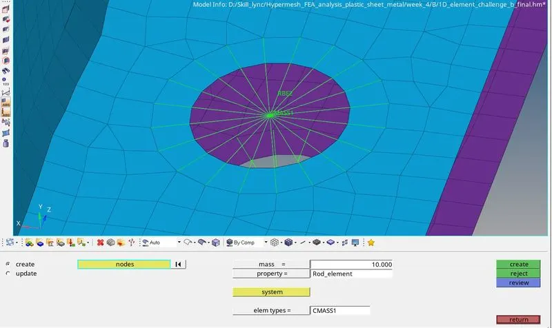
F. Join the two components with Spring elements
To apply spring element. Goto 1D > springs
Now, select the corners and middle nodes of top bracket similarly select the corners and middle nodes of bottom bracket to make a spring element as shown below.
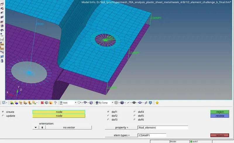
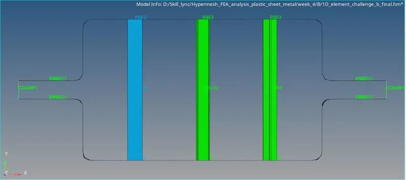
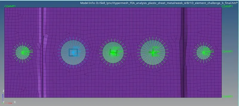
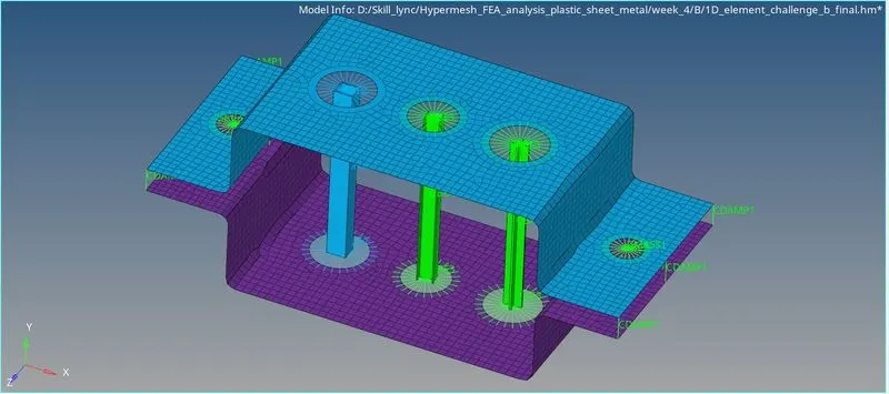
Final Model Views
Front View
Top View
ISO Metric View
CONCLUSION:
Hence, initially we have created the midsurface and meshed the given component with the element size of 5 Units and Created 1D elements of Rob, Beam, Bar, Mass and Spring on the given component with given cross-section and DOF as shown above.
DRIVELINK: https://drive.google.com/drive/folders/1CU8xxb2Xf8L-Qr_WTKsvfTxzEFn7NAtQ?usp=sharing