Week 4-1D Element Creation Challenge
OBJECTIVE: Create mid surface of the bracket and mesh it and create 1D connectors as specified below.
a. Translational DOF should be Constrained with RBE2 link Cross-Section: BOX.
b. All DOF should be constrained with RBE3 link Cross-Section: I Section.
c. Constrain only x and y DOFs With RBE3 link Cross-section: X section.
d&e. Apply the mass of magnitude 10 with the RBE2 link.
f. Join the two components with Spring elements.
PROCEDURE:
Import the cad file using import option and select the file from browseer and click import and the CAD will be shown as below.
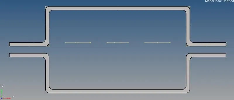
then delete all lines and solids in the CAD using delete option.
then create midsurface using midsurface option geom section of main menubar by creating two seperate components for two mid surfaces as below.
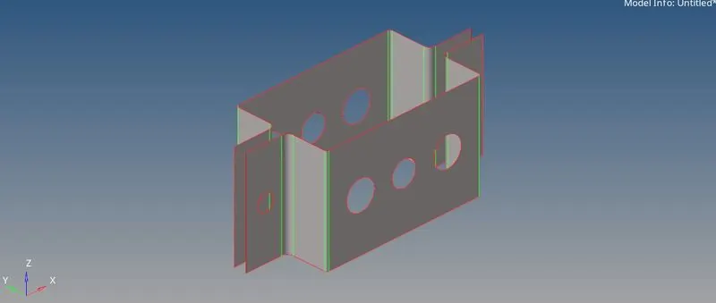
after this cleanup the midsurface using autocleanup option which removes unnecessary trim lines and creates washer trim around holes as shown below. make sure that the target element value does not differ between parameters and criteria.
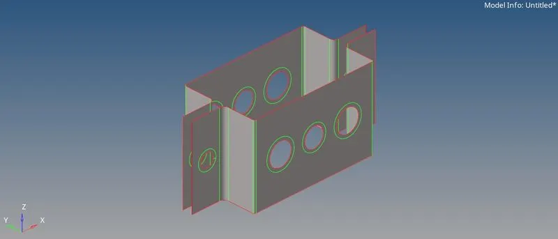
after this create mesh using automesh option in 2D section of main menubar and select surfaces and click mesh . and the 2D mesh is generated.
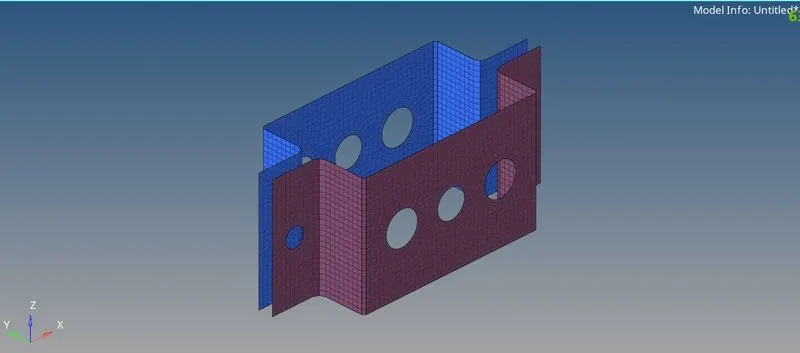
NOTE: create a new component and select that component in bottom right secton of hypermesh to assign the created component as our requirement.
now we have to create connectors. before that we have to create material, property cards and create cross section and assign it to the property card.
First create the material card giving the necessary values and now create property card for each connector rod, beam and bar and change card image to PROD, PBEAM and PBAR respectively. and create the cross section by HYPERBEAM option in 1D section and create them as instructed in video and assign the material card and beamsection respectively.
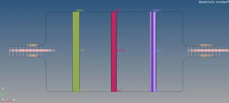
a.) now create connectors by first creating RBE2 Links for both holes ticking only translational dofs and connect the the two center nodes of two RBE2 links by rods option and assign the property card and element type as CROD.
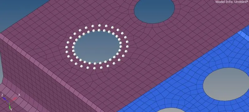
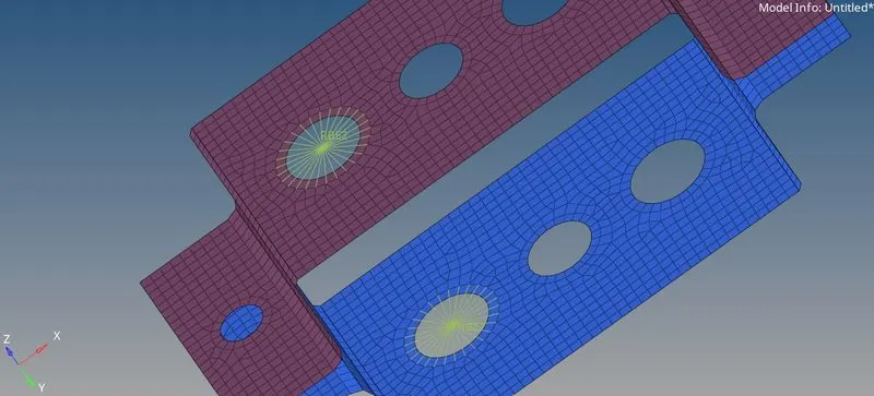
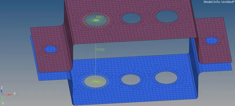
b.) now create RBE3 link at the middle holes with all and join those two elements with bars option in 1D secton and assign the property and element type as CBEAM and select the two center nodes of RBE3 nodes and cclick create the the connector is formed as shown below.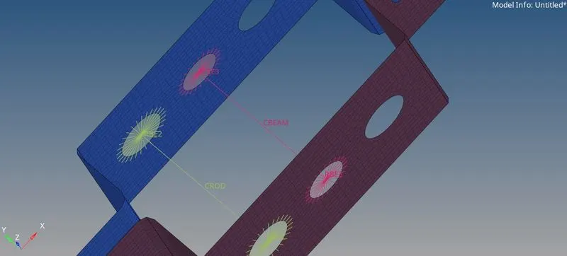
c.) now create RBE3 links as above with X and Y translational and rotatioanl dofs constrained and link these two links using bar option in 1D section and set element type as CBAR and assign property appropriate bar for it and create.
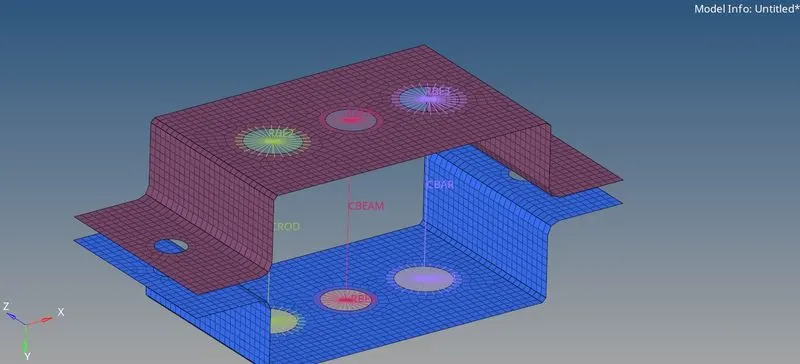
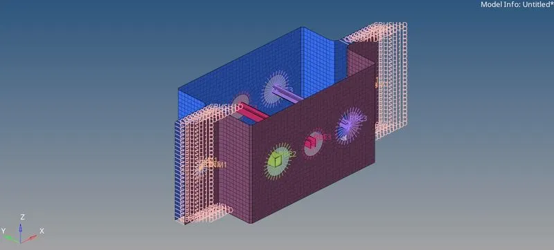
now enable 1D element detailed representation in view options to view the cross section and oreintation of 1D elements as shown below.
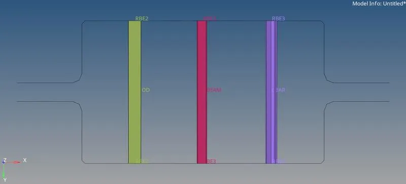
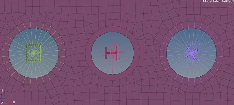
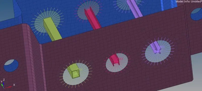
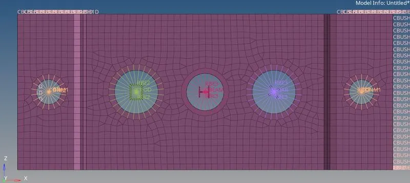
d.) & e.) now create the RBE2 elements on the four holes with all dofs constrained and create mass elements on center node of those four elements using mass option in 1D section with element type as CONM1 and magnitude 10.
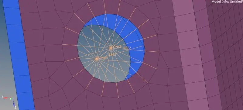
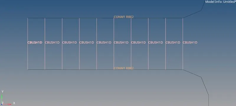
f.) now create spring elements between two nodes of each components choosing the elements type as CBUSH1D
as shown below.
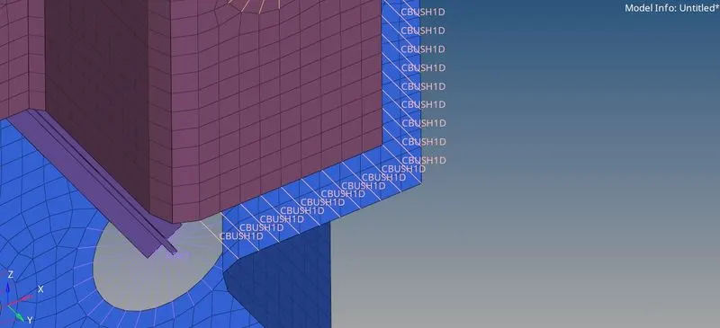
finally the whole FE element is as shown below.
WHAT I HAVE LEARNED....
I learned about various options of 1D section and how to use them and auto clean-up options. how to perform auto mesh in 2D section. and also to create beam sections, properties and materials along with assigning them.
CONCLUSION:
In this week I have performed auto cleanup and automesh on the given component and also practiced how to create the 1D elements and assign them an appropriate cross sections.