Week 4-1D Element Creation Challenge
THEORY:
Rigid elements are RBE2 elements which contain infinite stiffness that means these elements will never bend, never rotate.RBE2 elements will distribute the load equally to its elements but in RBE3 links, the load distribution is not uniform.
RODS are basically used for tension and compression.
In bars, all 6 degree of freedoms are used and used for symmetrical sections.
Beam is also similar to bar but also used for assymetrical section as well.
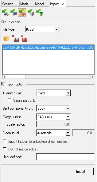
Firstly, we will import the CAD file in the hypermesh environment below image shows the procedure followed:
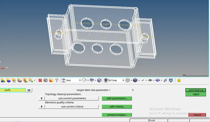
After importing, autocleanup is the procedure that is followed because there is certainities that the CAD file may have induced some errors while importing, So below is the image showing autocleanup:
Midsurfacing: midsurfacing brings out a single surface or shell from the 3d model. This technique is used because meshing of 3d model will be quite complex which can use hexa or tetra mesh indulging in increasing the storage capacity of the system. Whereas in midsurface, only 2d elements can be used.
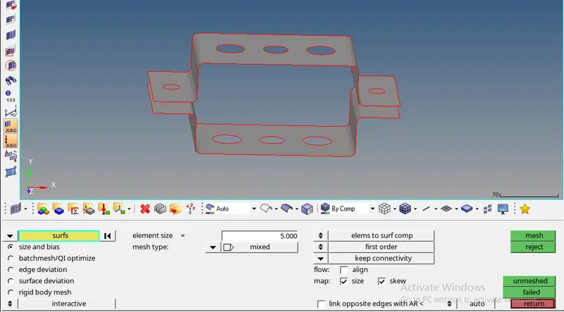
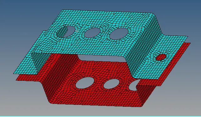
Below images shows the property and material assigned to the bracket1 and bracket2 of the component and also the final image after implementing the midsurfacing taking the element size as 5 units.
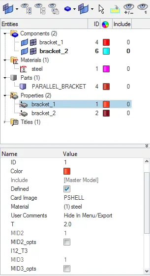
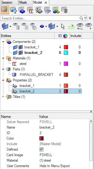
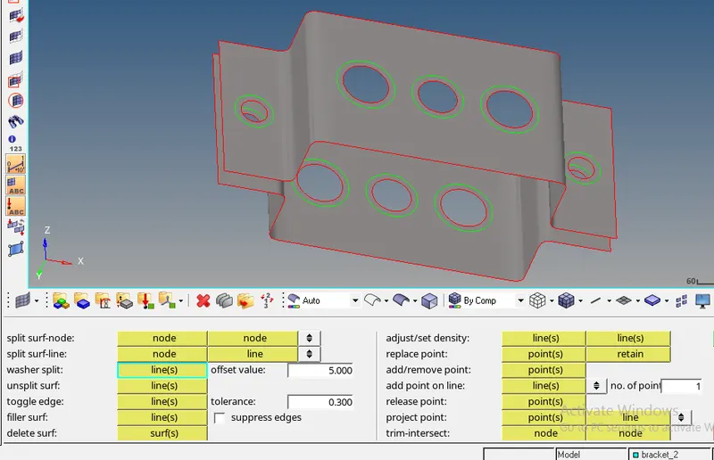
Washer split: Below image shows the washer splits applied to the holes of the component. These are applied so as to get better mesh quality.
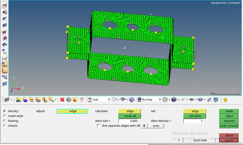
MESH: Mesh is made up of elements which containd nodes that represents the shape of the geometery and is one of the important step of FEA simulation. Below image shows the automesh applied to the component and final picture after the procedure.
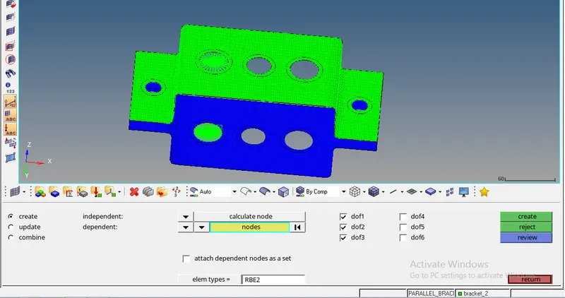
a. Rod element:- Translational DOF should be Constrained with RBE2 link
b. Beam element:- All DOF should be constrained with RBE3 link
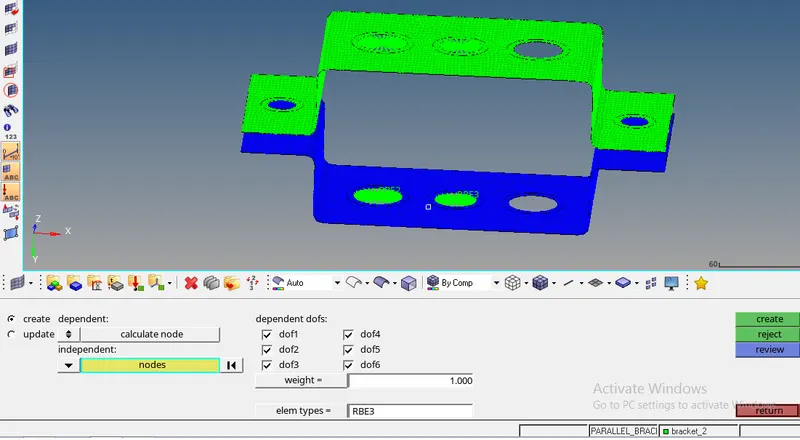
c. Bar element:- Constrain only x and y DOFs With RBE3 link
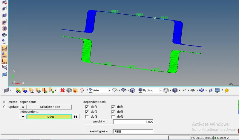
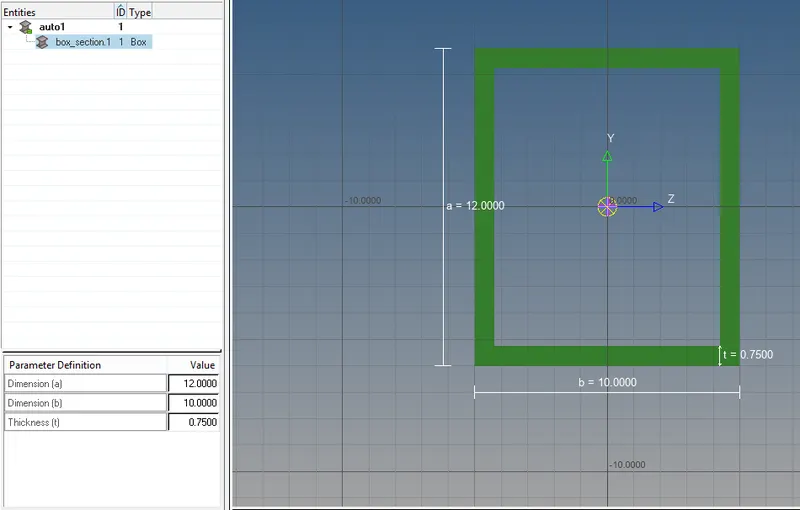
a) ROD ELEMENT(with translational dof and rbe2 link): Cross-Section: BOX- Dimension a= 12 mm
dimension b=10 mm
Thickness t= 0.75 mm
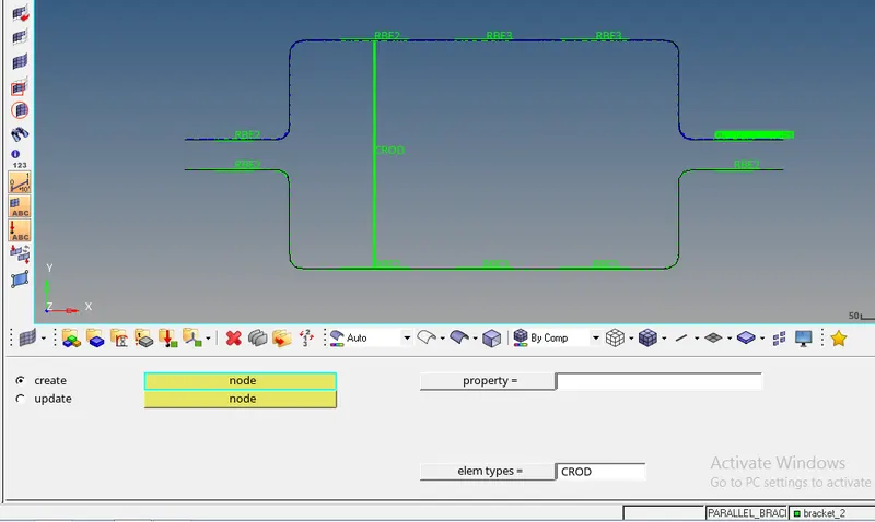
b. Beam element:- All DOF should be constrained with RBE3 link
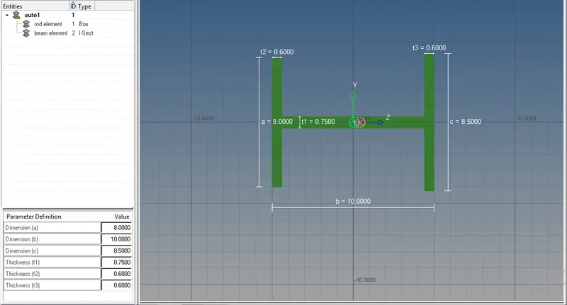
Cross-Section: I Section- Dimension a= 8 mm
Dimension b= 10 mm
Dimension c= 8.5 mm
Thickness t1= 0.75 mm
Thickness t2= .6 mm
Thickness t3= .6 mm
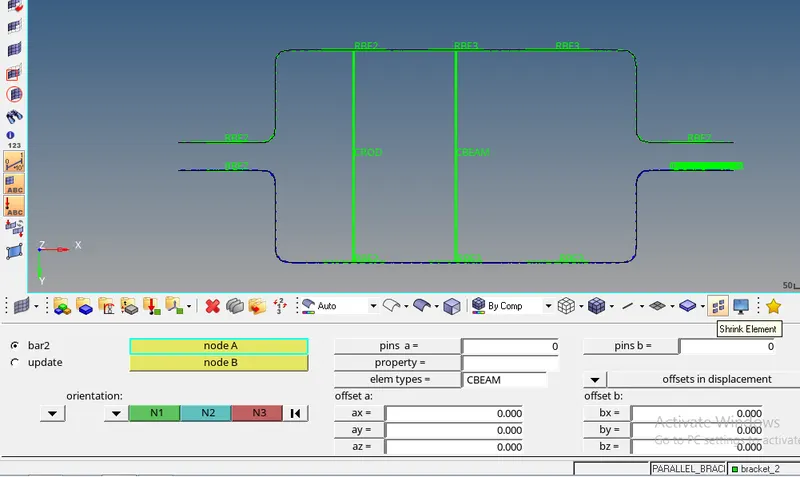
c. Bar element:- Constrain only x and y DOFs With RBE3 link
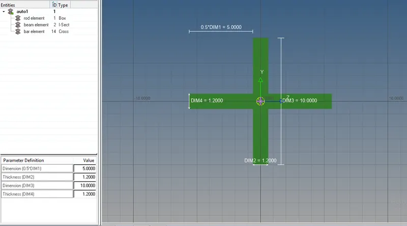
Cross-section: X section- Dimension DIM1= 5 mm
Thickness DIM2= 1.2 mm
Dimension DIM3= 10 mm
Thickness DIM4= 1.2mm
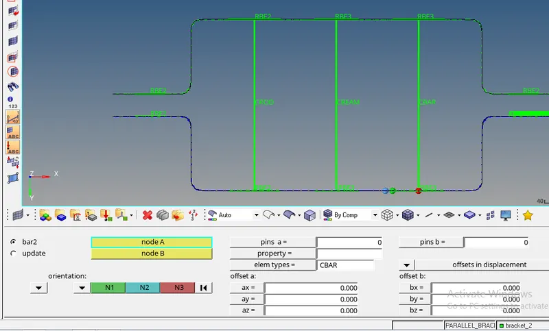
d. & e. Apply the mass of magnitude 10 with the RBE2 link
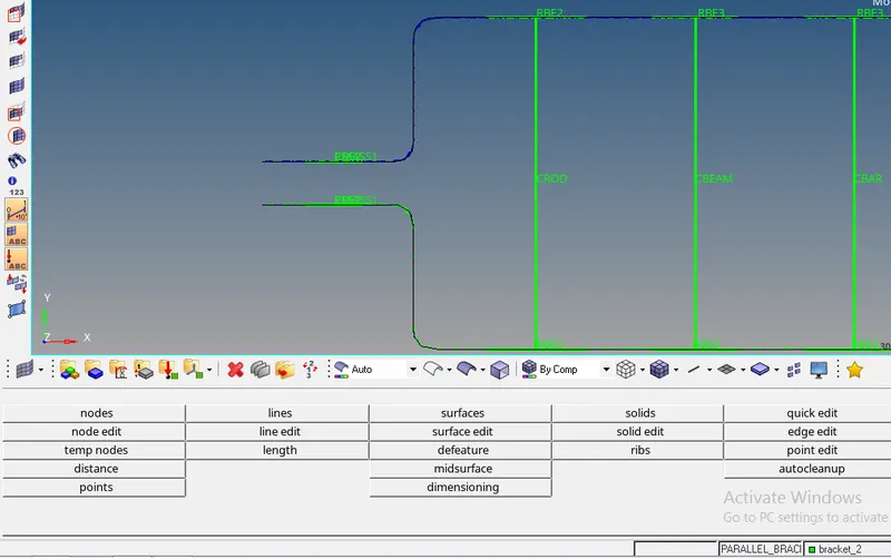
f. Join the two components with Spring elements