Week 4-1D Element Creation Challenge
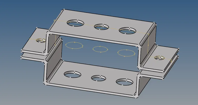
AIM: To create the 1D elements on the given component with a given cross-section and DOF with the Mesh size of 5 Units.
Objective:
- creating 1D elements on the given component with a given cross-section and DOF with the Mesh size of 5 Units. Also assigning properties, materials, cross sections, and elements on the specified areas.
- Rod element(a) - Translational DOF should be Constrained with RBE2 link (Cross-Section of the BOX with dimension a= 12 mm, dimension b=10 mm, Thickness t= 0.75 mm)
- Beam element(b)- All DOF should be constrained with RBE3 link (Cross-Section of I Section with dimension a= 8 mm, dimension b= 10 mm, dimension c= 8.5 mm, thickness t1= 0.75 mm, thickness t2= 0.6 mm, thickness t3= 0.6 mm)
- Bar element(c)- Constrain only x and y DOFs With RBE3 link (Cross-section of X section with dimension DIM1= 5 mm, thickness DIM2= 1.2 mm, dimension DIM3= 10 mm, thickness DIM4= 1.2mm)
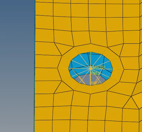
- Apply the mass of magnitude 10 for d & e with the RBE2 link
- Join the two components with Spring elements for f.
Procedure:
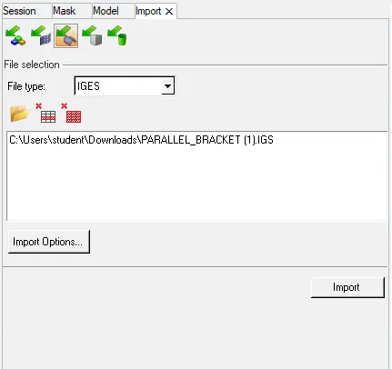
- Import the model to the hypermesh window by import option function. We have to check before whether the file is in which format.
- Here, the model is in IGES format and switching to Iges and then import the model to the hypermesh window.
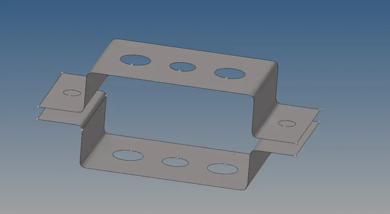
- The Model which we have to work on is shown below.
- Here the solid presence in the component is deleted before extracting the mid surrface.
- After extracting the mid surface from the model, the extracted mid surface is shown in the figure.
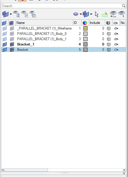
- New IDs are created for the Parallel brackets and they are named Bracket (1), Bracket(2).
- After extracting the mid surface from the solid surfaces, we have to check whether the surfaces are even and if there are any pinholes present on the mid surface.
- If they are pinholes present on the mid surface, then we have to washer split for better mesh.
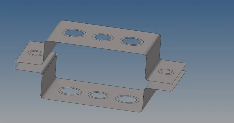
- The washer split creates an edge to apply the better mesh without disturbing the surfaces and to avoid trias.

- The image shown below is the mid surface which is applied with washer split.
- Assigning material card for the mid surfaces 1 and 2.
- Assigning properties by right clicking on the left side tab to create the property or material.
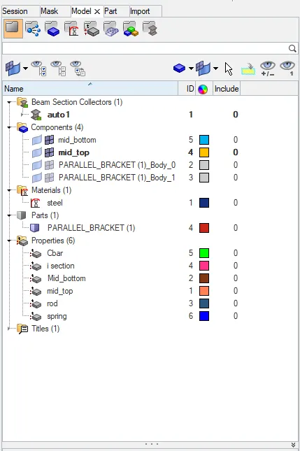
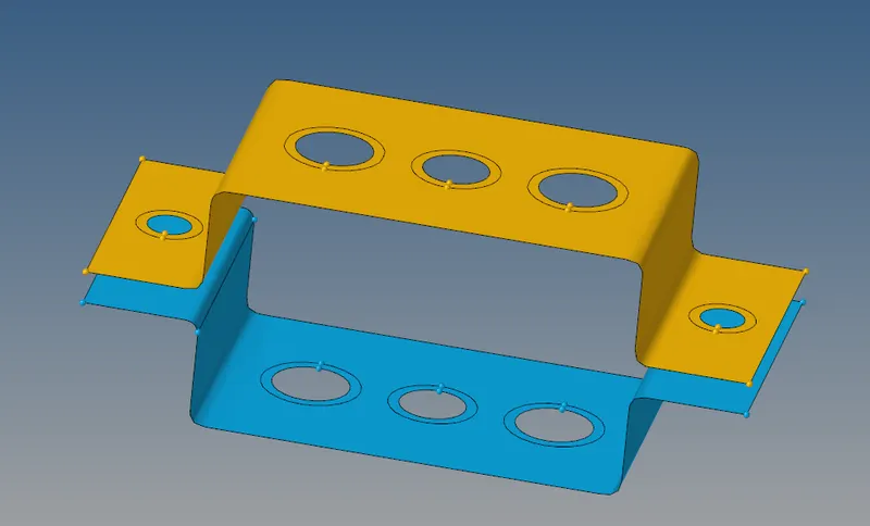
- These are the menu platforms wich mostly used in this process.


- Applying the mesh parameters with a element size of 5 units, the actual meshed component is shown in the figure.
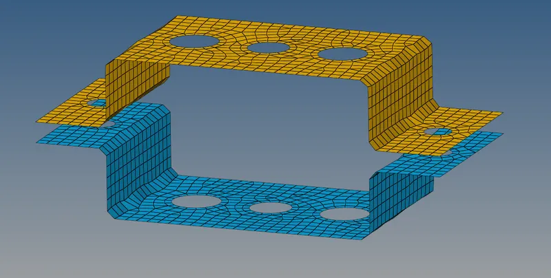
- Here, the mesh is created with 2D elements.
- We have to check for quality index of the mesh which we have generated.
- By switching to 2D > quality index.If there are no quality indices we can move forward for connections.
- Now we have to create the Rbe2 elements at a.
- Rigid elements are basically RBE2 elements. These elements have infinite stiffness. These elements never bend, rotate, or move. In RBE2, the load distribution is uniform irrespective of the position from the load.
- Translational DOF is Constrained with RBE2 at 2. While giving connection untick the rotational degree of freedom which are dof4, dof5, dof6. By clicking on the create button, it will the rigid elements(rbe2) as shown in the figure.
- Similarly the same way for d and e elements.

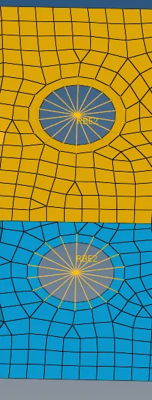
- Now we have to create the Rbe2 elements at b.
- It can be moved up, down, forward, bacward as per applied load. RBE3 elements are created same way as RBE2 elements.
- In RBE3 elements, the load distribution depends on the distance from the load. Load distribution is more on the nodes closer to the load.
- Now create RBE3 elements at b (all dof’s constrained).

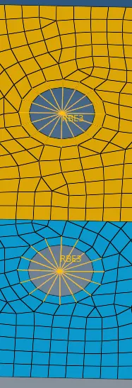
- Similarly at c, only x and y DOFs With RBE3 link are to be selected as shown in figure.
- It means there are no translational and rotational motion in z direction.

- Rbe3 elements at c with required motions are shown in figure.
- Now create the box Section at a with the given dimensions (a= 12 mm, b=10 mm, Thickness t= 0.75 mm)
- Go to 1D > Hyper beam > Standard section > select section library and type > Create
- Then,it will take to the hyperbeam window where we can edit all the dimensions of the section which we have given.

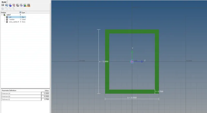
- At the time of creating the cross sections, create the propety of the materials which u have created.
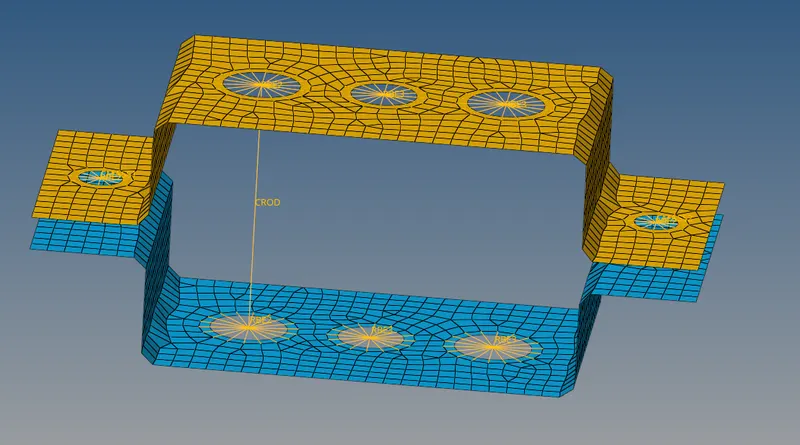
- The property of the rod section is created which will be used to define the property while creating the rod in the parallel bracket.
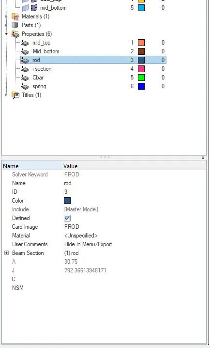
- Similarly, create the I section according to the required dimensions.
- Cross-Section of I Section with dimension a= 8 mm, dimension b= 10 mm, dimension c= 8.5 mm, thickness t1= 0.75 mm, thickness t2= 0.6 mm, thickness t3= 0.6 mm
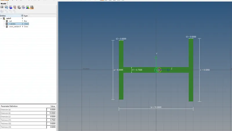
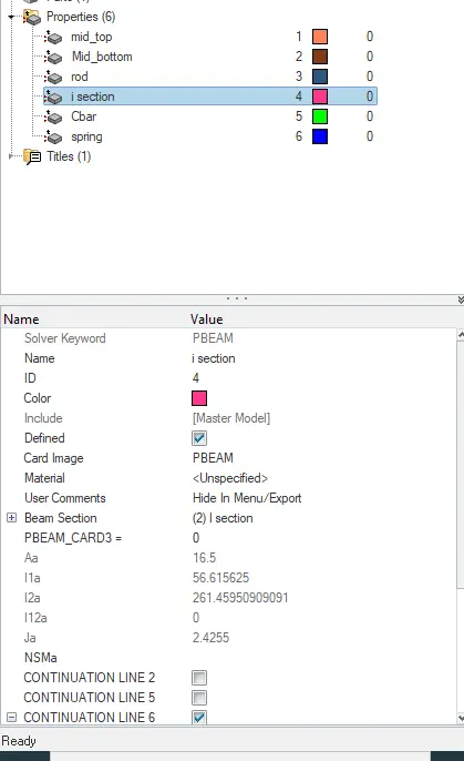
- Similarly for the I section, create the property card.
- Similarly, create the X section according to the required dimensions.
- (create > standard selection > optistuct> CROSS for X section)
- Cross-section of X section with dimension DIM1= 5 mm, thickness DIM2= 1.2 mm, dimension DIM3= 10 mm, thickness DIM4= 1.2mm.
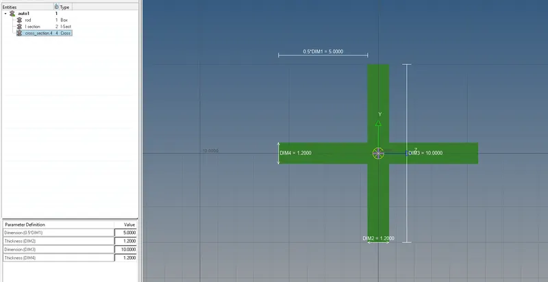
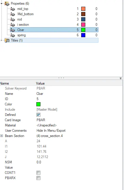
-
Assigning the hyper beam sections to 1D elements(connections). Create 3 separate properties for CROD, CBEAM and CBAR.
-
Here the 1Dimensional elements are to be created with the help of 1D options which is shown below.
- By clicking on the bars, the below options will appear to create rod at a.

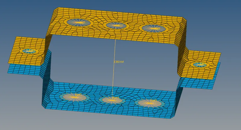
- Similarly at b, I section of the beam is created.

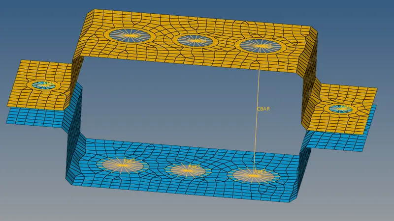
- Similarly at c, cross section of the bar is created.\

- To get to know about the sections which we have created, switch to 1D detailed representation view so that the created sections will be visible to us.

- Now we have to create the mass of magnitude 10 for d & e with the RBE2 link at d & e.
- Creating the property before assigning with one another.
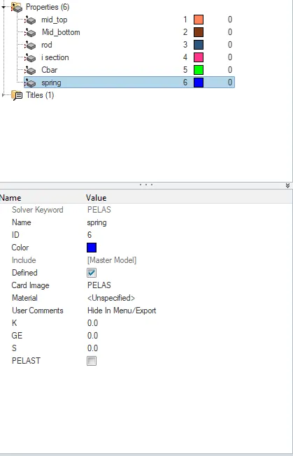
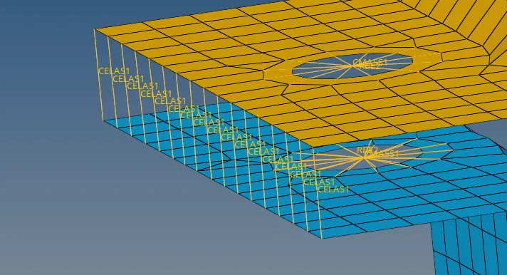
- To join the two components with Spring elements for f, we have to springs option in the 1D elements.
- Generally springs are elastic elements.
- we have to select the element type as CELAS and the property which we have created before creating the spring elements.
- Select the two nodes in between the two brackets and assign the property as spring and click on create to create them..

- Finally, the desired component is created with the help of given dimensions.
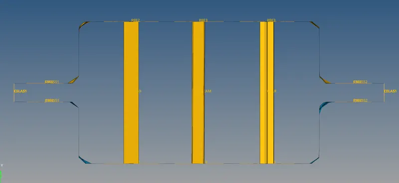
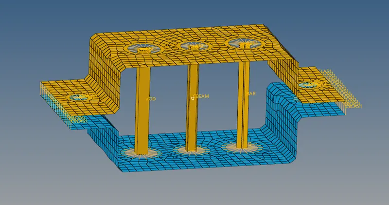
Result :
In this session created the cross sections,
- Rod element (a) created with only translational DOF and RBE2 link.
- Beam element (b) created with all DOF and RBE3 link.
- Bar element (c) created with only x & Y DOF and RBE3 link.
- Mass added on the Master node of RBE2 link at d & e .
- Two Components were joined with Spring Elements at f.